- Shopping cart 0 You have no items in your shopping cart.
- Check Order Status
- Inboard Boat Props
- Outboard Boat Props
- Sterndrive Props
- PWC Impellers
- Ski/Wake Props
- Authentic Volvo Duo Props
- Propeller Pullers
- Propeller Guides
- Brass cutless bearings
- Non metallic bearings
- Duramax flanged bearing
- Stave bearings
- Shaft Zinc Anodes
- Rudder Zinc Anodes
- Plate Zinc Anodes
- Shaft Nut Zincs
- Stainless Prop Shafts
- Shaft Seals
- Marine Shaft Logs
- Shaft Packing Boxes
- Shaft Accessories
- Deck Hardware
- Drivetrain Hardware
- Marine Exhaust Fittings
- Hose and Clamps
- Steering Hardware
- Marine Valves
- Plumbing Fittings
- Prop Shafting Accessories
- Marine Strainers
- Miscellaneous Hardware
- Shafts & Seals /
Aqualoy Marine Propeller shafts undergo more quality controls than any competing brand. These prop shafts are used in a wide variety of applications such as work boats, pleasure craft, naval vessels, and pumps. The Aqualoy process produces a rounder, straighter, stronger shaft. Aqualoy stainless shafts are available in A17, A19, and A22. Our stainless steel inboard propeller shafts from 3/4" - 4" diameter are precision machined in our Mazak Nexus 350M CNC turning lathe to insure all machining is within .0005". All propeller tapers are precisionally cut to SAE J755 specifications unless requested otherwise by the customer.
Deep Blue Yacht Supply is known throughout the marine industry for the quality of their stainless steel shafts. All shafts are packaged to the highest standards, and haven't had a single damaged shaft in the past decade of producing the finest propeller/pump shafts in the industry.
- Cutlass Bearings
- Boat Hardware
- 1-800-454-6960
- 1-321-978-0253
- 1-954-444-6259
- [email protected]
- DeepBlueYacht
- Contact Us With Questions
- Shipping and Return Policy
- Privacy Policy
- Conditions of Use
- Company Overview

Marine Propeller Shaft – Design And Construction
The heart of any ship lies in the engine room. Powered by large marine engines usually running on diesel oil of HFO, vessels are able to reach speeds of up to 50 kmph.
The components responsible for actually moving the ship are the large multi-blade propellers fit at the back.
So how does power transfer from the engines located deep inside the hull of a vessel to the propellers at the aft?
The answer lies in an integral mechanical component known as the marine shaft or propeller shaft.
Similar to how driveshafts work in cars, the shafts in ships also transfer rotational power from the engines to the propellers, which convert them into translational motion.
In this article, we will look at the marine propeller shaft and its various components, along with their design and construction, we will also study the working mechanism of these shafts.
How Are Ships Propelled?
The propulsion systems onboard ships power the vessel by converting rotational motion into translational motion. This is similar in theory to the famous Archimedes’ Screw mechanism credited to the Greek Mathematician Archimedes in c. 234 BC.
The rotational energy is provided by two to four marine engines located in the engine compartment of a ship. Both two and four-stroke engines are used depending on the size and required use of the vessel.
The marine engines generally run on diesel, although attempts are being made to turn to energy-friendly alternatives.
Inside the engine, pistons combust the fuel through alternating compression and expansion cycles. The combustion is achieved at ignition temperature and forces the crankshaft to make half a rotation under compression. The expansion phase completes the remaining half of the rotation.
The most commonly used type of marine engine is the reciprocating diesel engine that has a higher efficiency compared to other models. These engines can be classified into three types based on their revolutions per minute (rpm).
The three categories- slow, medium, and high speed have their own benefits based upon the type of ship to be powered.
For instance, large ships require a low speed but high torque propulsion system to power them. For such vessels, a low output speed engine can be selected.
The issue with using slow-speed engines is the large space they take up as compared to the other engines. Thus, a space-effective solution would be to install high-speed engines in the ship, and then reduce the torque before it reaches the propellers.
For this, a gearbox is a very useful component that can be used to manipulate rotational torque transfer. It is attached to the marine propeller shaft and reduces the power transmitted to the propeller.
The slow speed engines pose no problem to the transfer of torque and do not require an additional gearbox. The gearbox in the other speed engines is attached in between the intermediary and propeller shafts.
Components of Propeller Shafts
The marine propeller shaft is divided into three main components-
- the thrust shaft,
- intermediate shaft(s), and
The thrust shaft is the primary shaft emerging out of the engine. It directly receives the rotational motion from the crankshaft and rotates at the maximum velocity in high-speed engines.
For high rpm engines, the thrust shaft is further connected to other components that lie further aft.
The next component is the intermediate shaft. There is no specific restriction on the number of intermediary shafts that a ship can have. However, beyond 2 shafts, it can be difficult to service and maintain. The reason for this is the large catenary force acting on the entire propeller shaft. This force tends to deform and damage parts due to their weight.
When coupled with the large vibrational shocks that act on the shafts, there could be permanent damage to the propeller shafts. Thus, a low number of intermediary shafts are preferred. The only reason to have multiple intermediary shafts as if the engines are located far away from the propellers.
The last part is the tail shaft . It is directly connected to the propellers and lies mainly encased in the stern tube . The tail shaft is connected to the intermediate shaft by a gearbox that manipulates torque transfer. The tail shaft is built to withstand a variety of forces that may act at the stern of the ship.

The next component is the coupled bearing that connects two adjacent shafts. The coupling is achieved by virtue of joints that are usually rigid and do not flex. The coupling units are bolted to each other using high strength fasteners that can withstand a large number of vibrational stresses.
Shaft bearings are components that are used to support and bear the load of the shafts. They run along the length of the shaft and ensure smooth rotation. These bearings are constructed differently based on their location.
The last part of the marine propeller shaft system is the thrust blocks. These blocks support the propeller shafts at regular intervals. These blocks play transfer the excess power from the shafts into the hull of the ship.
As the shafts rotate at very high speeds, some amount of vibration occurs. This further leads to jarring shocks that may compromise the structural integrity of the vessel . Thus, using specialized bearings, the shocks can be dispersed over the hull of the ship.
To anchor these thrust blocks to the bed of the ship, a reinforced frame is built. There is a primary thrust block placed aft of the engine crankshaft, that disperses the majority of the shock into the hull girders and structures.
The components discussed above form the large bulk of parts that make up the propeller shafts. In addition, there are a variety of smaller parts such as sealants and bearings that serve different functions.
Design and Construction
The design and construction phase are important as it ensures structural strength. With shaft speeds reaching anywhere between 300 rpm to 1200 rpm, care must be taken to control material fatigue and reduce damages caused to the components of the ship.
The construction of the shaft bearings is important, as this holds the complete weight of the propeller shafts.
There are two main types of bearings- the full case bearing located at the stern, and the half case bearing located at the other positions.
The full casing provides a complete bearing for the weight of the shaft and is an integral part. The reason it is located at the stern is to account for both catenary weight forces, and also to counteract any buckling or reverse thrust forces felt at the aft due to the motion of the propellers. This bearing is also known as the aftmost tunnel bearing, as it encases the shaft just like a tunnel.
The other shafts only account for the weight, and hence do not require an upward casing unit. These bearings must be designed of high strength metals that do not easily buckle or deform under high strains. In addition, low levels of tolerances are expected during the manufacturing stage.
Special bearing pads are fit into slots on the connecting inner face of the bearing, such that it allows for smooth rotation. To lubricate the shaft bearing, an oil dip arrangement is carried out. By coating the rotating surface with oil from an oil thrower ring at regular intervals, a thick coat of lubrication is maintained at all times.
The coolant used to prevent overheating and subsequent damage are water circulated about the shaft bearing. This is stored in specialized tubes that run along the bearing and shaft. Tanks stored above the engine platform house coolant that is circulated around the propulsion machinery and systems.

The thrust blocks are used primarily to dampen and absorb forces from the rotating propeller shafts. These forces are redirected into specialised frames that make up the bed of the engine compartment. The energy in these frames is further distributed into the surfaces of the hull through the hull girders.
The hull girders serve as the framework on which the hull of the ship is constructed. The thrust blocks must be rigidly mounted in place to prevent any form of vibration during the course of the journey. Also, the primary thrust block can either be an independent unit that is built separately or can be integrated into the marine engines itself.
By integrating the block into the engine, it reduces the space requirements and maintenance costs while sailing. However, maintenance, while berthed, can be an issue as it would require opening the engine block casing. The casing that makes up the thrust blocks are built in two parts- an upper half that is detachable, and a lower half that supports the shaft.
The shaft is laid onto the lower block, and the upper half is then bolted into place using specialized fasteners that can absorb shock. To lubricate the rotating shaft, oil is regularly coated on to the rotating surface. This is achieved in a manner similar to that of the shaft bearings.
An oil thrower and deflector are put in place to maintain a constant supply of oil from a storage unit located on the lower half of the thrust block.
The operating temperature is controlled using cooling coils that circulate a chosen type of coolant throughout the block. It also draws coolant from the central propulsion cooling system. To absorb the vibrations and shocks, bearing pads are attached to the blocks.
They can be of two types- tilt pads, or pivotal pads, both of which are held in specialized holders built into the thrust block. The thrust pads transfer energy to the lower half of the casing that is constructed to withstand larger amounts of shock.
A thrust collar is also used to absorb thrust from the propeller shaft. The thrust blocks incorporate integral flanges that primarily help in bolting the block to other surfaces.
For instance, the block can be connected to the gearbox or engine using this flange. It can also be used to connect the engine thrust shaft to the intermediate shafts using these flanges. In case the thrust block is built into the engine block, it is made of the same casing material that the engine base plates are manufactured from.
In addition, they directly use the lubrication and coolant from the engine components itself. The integrated block is similar to the normal thrust blocks in most other features. It is interesting to note that the thrust block is integrated into the engine in most ships, except for the smaller boats that have space constraints.
The shafts themselves must be built from robust materials with high yield strength, and a lower probability of buckling. Each shaft starting from the thrust shaft must be built into small and manageable components that can be disassembled when the need arises.
In addition, seals and stuffing boxes are also built from appropriate materials that can effectively seal the inner working machinery from external water. High-grade materials are a must while manufacturing propeller shafts, as this is very sensitive equipment that needs to handle large forces.
The marine gearbox is an integral component that is attached in between the tail shaft and the intermediary shaft. It is mainly used to manipulate the torque transferred from the engine crankshaft to the propellers located at the stern. It is most commonly used in large vessels that engage a high-speed engine during operations.
The gearbox works just like an automobile gearbox, that uses a system of clutch discs and pads to control torque. Using robust gear arrangements that can withstand large vibrations, the gearbox is an integral part of ships with high-speed engines.
Lubrication is a necessity to prevent friction-related accidents or damage from occurring.
Stern Tube and the Propeller Shafts
Stern tube arrangement refers to the manner in which the tail shaft is borne by the stern tube that is located at the aft of the vessel. The stern tube is a hollow, horizontal tube that serves as the primary connection between the propellers and the rest of the vessel.
Attached to the stern frame , the stern tube acts as a plug at the rear of the vessel. The stern frame is the primary structural member that supports the stern overhang that lies above the propellers and rudder.
The stern tube houses the tail shaft of the marine drive shaft system and serves two main purposes- withstanding load and sealing the entire vessel at the aft portion.
Since the stern tube serves as the primary link between the vessel and the propeller, it must be able to withstand a tremendous amount of force that is exerted by the suspended propellers. In addition, it should provide sufficient room for the propeller hub to actually move without creating friction.
To handle the load, white metal is a commonly used material that can withstand the required loads. Sufficient lubrication is also provided within the stern tube to ensure the smooth functioning of the entire marine propulsion system.
Along with supporting the structural weight and forces of the propeller, the stern tube also needs to be able to effectively seal the vessel. It prevents water from entering through the aft and achieves this by using a combination of seals along its length. The stern tube has two main seals located at its aft and fore regions.
This serves as dual protection against any possible leaks that may occur over long periods of time. These seals can be of three main types- stuffing boxes, lip seals, and radial face seals. Stuffing boxes are built out of a variety of packing materials that are used to plug the stern tube.
Lip seals are gland seals that are used to prevent lubricants from seeping out into the water. They also serve the dual purpose of preventing water from entering the stern tube. Lastly, radial face seals extend radially out from any points of ingress and use a spring system to seal the entire structure. They are composed of two main parts that join to completely seal the rear portion.
The stern tube plays an important role in marine propulsion since it absorbs and dampens a considerable amount of power away from the propeller. In an effort to completely seal the stern section of the ship, it may also hamper the rotational abilities of the propeller shafts.
This would be counterproductive and would create a large amount of stress within the hull of the ship. Thus, being able to effectively seal the aft region without affecting the performance parameters is a major necessity in naval architecture and engineering.
Do you have info to share with us ? Suggest a correction

About Author
Ajay Menon is a graduate of the Indian Institute of Technology, Kharagpur, with an integrated major in Ocean Engineering and Naval Architecture. Besides writing, he balances chess and works out tunes on his keyboard during his free time.
Read More Articles By This Author >
Related Articles

9 New Aspects of IACS Harmonised Common Structural Rules (CSR) For Ships
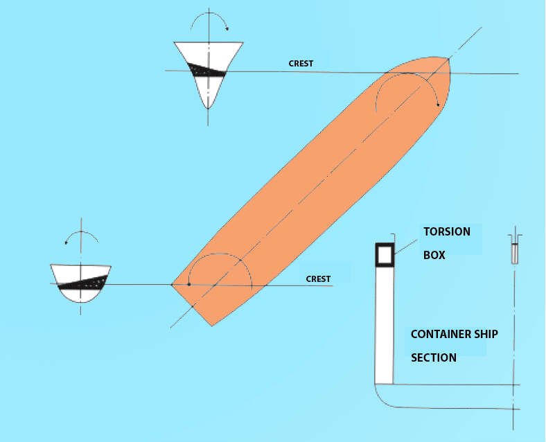
What Is The Purpose Of “Torsion Box” In Ships?

Types of Bow Designs Used For Ships
Daily maritime news, straight to your inbox.
Sign Up To Get Daily Newsletters
Join over 60k+ people who read our daily newsletters
By subscribing, you agree to our Privacy Policy and may receive occasional deal communications; you can unsubscribe anytime.
BE THE FIRST TO COMMENT
Thank you very much for this article. You explained marine propulsion and shaft in a clear manner.
Thank you very much for this information
Leave a Reply
Your email address will not be published. Required fields are marked *
Subscribe to Marine Insight Daily Newsletter
" * " indicates required fields
Marine Engineering
Marine Engine Air Compressor Marine Boiler Oily Water Separator Marine Electrical Ship Generator Ship Stabilizer
Nautical Science
Mooring Bridge Watchkeeping Ship Manoeuvring Nautical Charts Anchoring Nautical Equipment Shipboard Guidelines
Explore
Free Maritime eBooks Premium Maritime eBooks Marine Safety Financial Planning Marine Careers Maritime Law Ship Dry Dock
Shipping News Maritime Reports Videos Maritime Piracy Offshore Safety Of Life At Sea (SOLAS) MARPOL
WAIT! Did You Download 13 FREE Maritime eBooks?
Sign-up and download instantly!
We respect your privacy and take protecting it very seriously. No spam!
WAIT! Did You Download 12 FREE Maritime eBooks?
- My account Close My account Log out
- Compare products list
You have no items in your shopping cart.
- Inboard Propellers
- Outboard Propellers
- Stern drive boat props
- PWC Impellers
- Ski Wake Boat Props
- Volvo Duo Props
- Prop Pullers
- Prop Guide & Sizings
- Brass cutless bearings
- Non Metallic
- Flanged bearings
- Stave bearings
- Shaft Zincs for sale
- Rudder Boat Zincs
- Plate Zincs
Stainless Steel Shafts
- Shaft Seals
- Packing Boxes
- Shaft Accessories
- Deck Hardware
- Drivetrain Hardware
- Exhaust Fittings
- Hose and Clamps
- Steering Hardware
- Plumbing Fittings
- Shafting Accessories
- Miscellaneous Hardware
- Michigan Wheel
- Zimar Zinc Anodes
- Tides Marine
- SOLAS boat propellers
- ACME Marine
- Volvo Penta Duo Props
- Buck Algonquin Marine Hardware
- Shafts & Seals /
Propeller Depot is known throughout the marine and pump industry as producing the best stainless shafts; at the best possible pricing, with the best quality. Our stainless shafts come in A17, A19, and A22; and can be shipped across the globe. Order your inboard prop shaft today and save hundreds to thousands. Propeller tapers are cut to SAE J755 standards.
- 48-13702A46
- 48-16314A46
- 48-16316A46
- 48-16318A46
- 48-832828A45
- 48-832830A45
- Get in Touch
- Shipping and Return Policy
- Privacy Notice
- Conditions of Use
- Customer info
- Shopping cart
Payment options

How to Choose a Sailboat Propeller: An Essential Guide
There is perhaps no sight more graceful than a sailboat gliding across the water. Did you know that in addition to sails, sailboats also have engines? A sailboat’s engine and propeller enable it to maneuver in and out of a marina or harbor, and also to sail under power when the wind is uncooperative or blowing from the wrong direction (i.e., the same direction that the sailboat is headed).
But how to choose a sailboat propeller? There are several important considerations to keep in mind starting with your budget and needs. Fixed blade propellers are the most economical option but produce a lot of drag when under sail, while folding and feathering propellers produce less drag but are more expensive.
With the right propeller, a sailboat’s performance under sail can be optimized as far as speed and minimal engine wear, while being efficient and highly maneuverable moving forward and in reverse under motor power.
The Different Types of Propellers
Ideally, you want to achieve maximum power, or thrust, and optimal engine efficiency when the sailboat is moving under power, and zero drag while under sail. Drag is essentially a negative force that acts against the forward movement of the vessel, hindering speed, reducing sail and motor efficiency, and increasing wear on engine and propeller components.
Drag in the context of sailing is created by the propeller while the sailboat is moving under sail. Because the propeller is an immovable object attached to the stern (rear) of the sailboat, it creates a substantial amount of resistance in the water. Sailors liken the effect of propeller drag to towing a large bucket under water, or driving a car downhill with the brakes engaged.
There are three primary categories of sailboat propellers, (1) fixed blade propellers, (2) folding propellers and (3) feathering propellers. Each type has its benefits and limitations, and the price range vary widely from one to another.
Fixed Blade Propellers
This is the most common type of sailboat propeller and is typically the type of propeller that is pre-installed by manufacturers. As the name suggests, fixed blade propellers have two or three (sometimes four) blades that are arranged in a fixed, unadjustable position. Because they are the simplest in design and the easiest to maintain, fixed blade propellers are typically the most economical option for sailors and deliver the most bang for your buck.
As far as forward thrust goes, fixed blade propellers perform well, but when operated in reverse (such as maneuvering into a boat slip), they perform poorly, losing as much as 50% of the thrust. This is due primarily to the fact that when the propeller is run in reverse with blades that are fixed, the trailing edge of each blade must act as the leading edge, which is highly inefficient.
The main drawback of fixed blade propellers is the amount of drag they create while under sail. The negative effect that this type of propeller has on a sailboat’s performance can be put in several different ways:
- The amount of drag created by a fixed blade propeller can reduce a sailboat’s speed under sail by as much as 1 to 1 ½ knots
- Up to 20% of a sailboat’s speed can be reduced by dragging a fixed blade propeller underwater
- A fixed blade propeller can generate upwards of 70 pounds of pull in the opposite direction as the sailboat’s heading
- A fixed blade propeller’s drag can add one hour to a sailboat’s 20-mile daysail
Certain sailboat engines allow the sailor to disengage the transmission gear, thereby allowing the fixed blade propeller to spin freely while under sail. While this does reduce the amount of drag at certain speeds, the resulting wear on bearings and other transmission parts may cause more harm than good. For longer trips, it may be advisable to place the sailboat engine in gear or operate a shaft brake.
Folding Propellers
Folding propellers usually come in two or three blade configurations, although newer sailboats are outfitted with four blade propellers. Folding propellers have the lowest drag characteristics of all types of propellers and are a popular choice among sailors willing to pay substantially more than they would for traditional fixed blade propellers. (Although still less than feathering propellers.)
Another benefit of folding propellers, aside from their low drag quotient, is that their streamlined profile, when closed, allows the propeller to be less prone to getting entangled in kelp, flotsam, jetsam, or rope. Such items do pose problems for other types of propellers, and experienced sailors carry sharp knives to free their sailboats from entanglements, often involving fishing nets and crab pot lines in commercial waters.
When under sail and with the engine disengaged, the flow of water past the propeller forces the blades to fold inward with the tips of the blades pointing aft (toward the rear of the sailboat). When the sailboat engine is engaged and revved, the centrifugal force of the shaft spinning will cause the blades to open and propel the sailboat forward or in reverse.
Although engineering and design breakthroughs have greatly enhanced their performance, folding propellers are still shedding a bad reputation for being problematic, particularly with regard to:
- At low speeds while under sail, the pressure of water flowing past the propeller is not strong enough to push the blades into a folded position
- Blades can act independently of each other (e.g., one open and one closed), particularly two-bladed propellers that are in a vertical alignment where the top blade is closed, but the bottom blade is open due to the force of gravity
- The amount of centrifugal force needed to re-open the blades requires revving the engine to higher RPMs
- Very poor thrust when moving in reverse
Many of these problems have been resolved by innovations such as geared blades that are completely synchronized with one another and, therefore, open and close in unison. Recent blade designs have also made forward thrust even more efficient while improving mobility moving in reverse. Folding propellers are now featured standard equipment on many new sailboats from reputable manufacturers.
Folding propeller blades are not attached to the shaft in the same manner as fixed blade propellers and because the blades fold in and out depending on the sailboat’s speed, you can expect higher maintenance and repair costs associated with this type of propeller.
It should be noted that folding propellers may not be an option for larger sailboats with longer keels because these vessels often have an opening (called an aperture) between the rudder and the keel where the propeller sits. Because a folding propeller has blades that fold when under sail, the length of the folded blades may extend into the rudder.
Feathering Propellers
When under sail, the blades of a feathering propeller pivot in relation to the shaft so that the leading edges cut straight into the water with minimal drag. This type of propeller is by far the most costly option as far as sailboat propellers go, but depending on the sailor’s needs, it may be the best one as well.
When the engine is engaged, the torque of the propeller shaft causes the blades to pivot to a certain pitch to provide a highly efficient forward thrust. And unlike fixed blade or folding propellers, because of the unique pivoting action of the blades feathering propellers are nearly as efficient moving in reverse. This feature is particularly appealing to sailors who must navigate in and out of congested marinas or tight corners in cramped harbors.
Another feature offered by feathering propellers is the ability to adjust the pitch, or the blades’ angle of attack to the water, to best suit the engine to which it is attached. This will result in optimized thrust moving forward and backward and yield improved fuel efficiency.
In higher end models, this pitch adjustment is done automatically. As the engine revs, the pitch of the blades will adjust. In other versions, the adjustment must be performed manually with the propeller out of the water. But in either case, feathering propellers afford the sailboat owner the ability to pair the propeller’s performance with the sailboat’s engine capabilities, thereby producing a custom fit.
On the downside, aside from their cost, feathering propellers also have more moving parts than a fixed blade propeller. Although they are considered more robust than folding propellers because the blades do not fold in and out, the blades on a feathering propeller are mechanically attached to the shaft and rely upon internal mechanisms to pivot the blades straight under sail and in forward or reverse pitch.
Therefore, on top of the expense of purchasing one, you can expect that regular maintenance costs will exceed those associated with a fixed blade propeller.
Choosing the Right Propeller for Your Sailboat
Ultimately selecting the right propeller for your sailboat depends on your motoring needs as well as your budget. If maneuverability under power is an absolute must, then strong consideration should be given to a feathering propeller. If your main concerns relate to minimal drag under sail, then either a folding or feathering propeller may be options for you, with cost being the deciding factor.
If, however, you are looking for basic sailboat motoring and you occasionally go out for a leisurely sail around local waters, then perhaps a fixed blade propeller is the right choice for you.
It should be noted that in order to make a truly informed decision, you should look beyond the three main categories of sailboat propellers and consider specific characteristics of propellers such as diameter and pitch, which will provide you with the true performance parameters you can expect out of a propeller.
Will a Bigger Propeller Make Your Boat Faster?
In simple terms, when a propeller turns, its blades create displacement of water that generates thrust and propels the sailboat forward or backward depending on the direction of the propeller’s rotation. On most sailboat engines, forward motion correlates to right-handed rotation (the propeller turns in a clockwise direction when viewed from the rear of the vessel).
The hydrodynamics of a propeller’s blades propel the sailboat in much the same way that the shape of an airplane’s wing creates lift. The sailboat’s engine turns the propeller at varying speeds, which correlate to revolutions per minute (RPM). This rotation is converted by the propeller into thrust.
So, will a bigger propeller make your sailboat faster? Not necessarily. While a bigger propeller will have larger blades that, in theory, should produce greater thrust, the size and length of the vessel and the power and capacity of the sailboat’s engine must be considered. An underpowered engine would struggle to turn an oversized propeller and could become damaged in the process.
All propellers share the same primary characteristics, whether they are powering a sailboat, a luxury yacht or even a cruise ship. Some of these characteristics directly affect the thrust characteristics and overall efficiency of the propeller in specific relation to the sailboat engine on which it is installed.
Hub and Shaft
The hub is the central core of the propeller and is where the propeller blades attach. The hub, in turn, is attached to the propeller shaft, which is part of the sailboat engine’s drivetrain and rotates the propeller.
Propeller Blade Anatomy
Although today’s sailboat propeller blades come in a wide variety of shapes, their basic anatomy and how they function remain the same. Understanding the basic terminology of the various blade parts is instrumental in making an informed decision when selecting a propeller for your sailboat.
- The root is the innermost portion of the blade that attaches to the propeller hub. Since it is closest to the shaft, it travels the shortest distance per revolution. On the outermost edge of the blade is the tip which is the furthest away from the shaft and travels the longest distance per revolution and therefore undergoes the greatest amount of stress when the sailboat is moving under power.
- An important concept to understand with regard to propellers and blades is that the blade root and blade tip are different points on the same blade. Even though they are different distances from the hub, they still complete a revolution at the same time. This explains why the tip moves faster than the root, and this is particularly relevant to propeller pitch, which is discussed later.
- The blade face is the side of the propeller blade that faces aft (rear of the sailboat). Also referred to as the pressure side, the blade face pushes the water away from the propeller as the sailboat moves in a forward direction. In other words, water is forced away from the propeller, which is mounted at the rear of the sailboat, thereby propelling the vessel in the opposite direction.
- The blade back is the opposite side of the propeller blade that faces forward (front of the sailboat). This side of the propeller blade is often referred to as the suction, or negative pressure, side. As the propeller rotates, the blade back is the first surface of the propeller to come into contact with the water, and it creates a pressure differential which in conjunction with the blade face, creates thrust.
- The leading edge of the propeller blade is the forward portion that leads or cuts into the water first. As the propeller rotates, it generates the flow of water across the blade.
- The trailing edge is on the rear portion of the propeller blade adjacent to the aft side of the hub and is the edge of the propeller blade that exits the water flow. The leading edge and trailing edge must work together to produce clean, efficient thrust.
This is considered one of the more vital dimensions to differentiate one propeller from another (the other being pitch) and provide a quantifiable means of predicting performance. If you imagine a circle formed by the blade tips rotating, the diameter would be the length of the line (usually in inches) that passes from one edge of the circle, through the center of the circle and continuing to the opposite edge.
Although propellers with larger diameters are able to convert power into more thrust through the water, they must be properly sized to the sailboat’s engine and drivetrain due to the greater amount of power needed to drive the blades through the water. Larger diameter propellers run at lower revolutions per minute versus smaller diameter propellers, which typically run at higher RPM.
Another important consideration with larger diameter propellers is the increased amount of drag that they create under sail, particularly fixed blade propellers.
This refers to the distance that the propeller would travel in one full revolution if it were rotating in a solid medium with zero slippage. Pitch is usually indicated in inches, so if a propeller has a 20 inch pitch, then it would move 20 inches when turning one revolution. The pitch of a propeller can be likened to the turning of a screw into wood.
A propeller rotating in the water will not achieve perfect or full pitch because as the sailboat moves in the water, it experiences drag against its hull and the propeller. In other words, there is a loss of efficiency, and it can vary anywhere from 5% to 40%. The better the propeller is matched to the vessel and its engine, the lower the propeller slip value, and the greater the efficiency at which the propeller performs.
As with propeller diameter, the higher the pitch the greater the potential amount of thrust that can be generated by the propeller’s blades. The caveat, however, remains the same. A propeller’s pitch must be properly matched to the capacity of the sailboat’s engine and drivetrain. A mismatched pitch can result in very poor performance under power, or worse yet, serious damage to the propulsion system itself.
It should be noted that pitch is a broad and general term, or characteristic, with respect to sailboat propeller blades. There are specific types of pitch available, and each is worth considering.
- Constant Pitch – When the propeller blades have the same angle of attach toward the water from the root to the tip, they are said to have constant pitch. Constant pitch propellers tend to be more affordable because they are cheaper to manufacture.
- Variable Pitch – A variable pitch propeller blade has a higher pitch at the root of the blade and lower pitch at the tip producing a twisted shape to the blade. This variable pitch design is needed to produce an even thrust throughout the blade because the tip travels at a faster speed than the root and would, therefore, produce more thrust.
Of all the various characteristics of propellers, diameter, and pitch are the most important when it comes to efficiently creating thrust, and therefore, these are the measurements that should be carefully considered when choosing a sailboat propeller. Sailboat propellers are often stamped with two sets of numbers, the first being the diameter and the second being the pitch.
- Example : A propeller marked 20 x 16 would indicate a 20-inch diameter with a 16-inch pitch
Fuel Consumption Chart
Under ideal conditions, a sailboat would travel completely under sail with minimal time spent motoring under power. Unfortunately, sailors are at the mercy of winds, currents, and waves. As such, a sailor may be forced to cruise under power and sometimes for long or unknown stretches. It is, therefore, useful to know how much fuel a sailboat consumes when running under power.
There are various methods for estimating fuel consumption, which would also enable projecting range and engine running hours. One method is to estimate burn rate and then extrapolate estimated running hours based on the sailboat’s fuel tank capacity.
- Example : A common fuel burn rate that seems to apply to a broad range of engine sizes is .75 gallons per hour (GPH). If a sailboat’s fuel tank has a maximum capacity of 50 gallons, then dividing 50 by .75 equals 67 hours of sailing under power. However, it is important to note that this .75 GPH burn rate is under ideal weather conditions (no current, calm waters).
Unlike automobiles, it is virtually impossible to convey fuel efficiency for sailboats in terms of average distance per gallon of fuel (e.g., miles per gallon/MPG). This is primarily due to the many variables that a sailboat running under power would encounter, namely ocean currents, large waves, and head winds, any one of which could easily double the amount of fuel that a sailboat consumes.
The most common expression of a sailboat’s fuel consumption is stated in terms of gallons of fuel burned per hour . Sailboat engines have varying rates of fuel consumption depending on their size, typically indicated by number of horsepower (HP). As a general rule, the higher the horsepower, the greater the fuel consumption.
Here is a simple chart showing approximate fuel consumption rates (gallons per hour) for sailboats with different engine sizes (horsepower):
The above figures reflect estimated fuel consumption under benign weather conditions. In adverse sailing conditions, the fuel consumption figures above would increase by a minimum of 40%.
There are other factors that directly affect a sailboat’s fuel consumption and fuel efficiency, including:
- Sailboat Hull Size and Shape – The size, shape, and length of the sailboat’s hull will have a direct impact on fuel consumption and fuel efficiency. As a general rule, the more streamlined the shape, the less water that has to be pushed out of the way, and the less fuel that has to be consumed in the process. Water displacement is one way to quantify this.
- Engine Size – Engine size is another factor that directly contributes to a sailboat’s fuel consumption. The larger or more powerful the engine, the greater its fuel consumption. However, this is not to be confused with fuel efficiency. A larger engine may consume more fuel but yield more nautical miles traveled per gallon than a smaller engine that burns less fuel but runs at higher RPMs and therefore produces less range.
- Propeller Type – Certain propellers, as we have seen, produce more thrust and deliver power more efficiently than others. For example, a variable pitch blade will consume less fuel than a constant pitch blade.
- Hull Condition – A clean hull cuts through the water more efficiently than a dirty one and will consume less fuel.
- Weight – Heavy cargo can weigh down a sailboat and dramatically increase its fuel consumption rates.
- Adverse Weather Conditions – Weather conditions can have the greatest effect on a sailboat’s fuel consumption. Sailing under power into a strong current or headwind can double your fuel consumption, as can riding through strong waves.
- Over-revving the Engine – Revving the engine too high can unnecessarily burn fuel, not to mention increase wear on the drivetrain. Most sailboat engines achieve optimal running efficiency at 70-85% of maximum RPMs.
Now that you have learned everything you need to know to make a wise choice when it comes to selecting a sailboat propeller, now all you have to do is go shopping for one!
I am the owner of sailoradvice. I live in Birmingham, UK and love to sail with my wife and three boys throughout the year.
Recent Posts
How To Sail From The Great Lakes To The Ocean
It’s a feat in and of itself to sail to the Great Lakes. Now you want to take it one step further and reach the ocean, notably, the Atlantic Ocean. How do you chart a sailing course to get to the...
Can You Sail from the Great Lakes to the Gulf of Mexico by Boat? 
You have years of boating experience and consider yourself quite an accomplished sailor. Lately, you’ve been interested in challenging yourself and traveling greater distances than ever before. If...

- BOAT OF THE YEAR
- Newsletters
- Sailboat Reviews
- Boating Safety
- Sailing Totem
- Charter Resources
- Destinations
- Galley Recipes
- Living Aboard
- Sails and Rigging
- Maintenance
Sailboat Propeller-Shaft Couplings
- By Steve D'Antonio
- Updated: June 19, 2019

If you’ve ever aligned your propeller shaft and engine, then you’ve handled the hardware that connects these two components together: the shaft coupling. While simple in form, couplings play a critical role in drivetrain reliability. If they are not properly installed, they can lead to vibration or worse — the separation of the shaft from the engine.
There are three primary types of couplings: straight, split and tapered, with the first two being the most common for smaller sailboat auxiliaries.
While straight-bore couplings are common, they lack the grip required for larger engines and props, which can place significant strain on the shaft-to-coupling interface. The challenge is getting the interference fit between shaft and coupling bore just right. If it’s too tight, driving the coupling onto the shaft may be very difficult, and if it gets stuck before it’s fully inserted, that can present a challenge. If it’s too loose, the shaft may begin to shift in the coupling with each forward-neutral-reverse shift evolution, which in turn will gall the key, allowing for more and more movement.
This scenario often ends with a sheared key and set screws, with the shaft and prop sliding out the shaft log, at which point they either screw their way into the ocean depths or strike — and jam — the rudder. If the shaft parts from the stuffing box altogether, a fire-hose-like geyser will erupt, after which the bilge pumps will be tested, and not in a good way. Installing a clamp ring on the shaft to prevent this scenario makes good sense as a safety backup. Better still, set up your shaft and coupling properly, and you’ll never have to test the clamp ring.

Split couplings are easily identified by their bifurcated design. While this coupling is really made up of one part, its aft end is divided into two sections that are clamped against the shaft using two or more machine screws. With this arrangement, the coupling can apply clamping action to the shaft. The split coupling offers one advantage over other coupling types, as it enables easy removal of the shaft by driving a pair of steel wedges or cold chisels into the gap between the two split halves.
Beyond this, there is no other benefit to using a split coupling, and I’d argue that rather than making it easy to remove, the primary mission of a coupling is to securely retain the shaft. Additionally, because it is split, and therefore moves or distorts each time a shaft is inserted or removed, the coupling face may not remain perpendicular to the shaft, which will affect the ability of the shaft to be aligned to the engine/transmission output coupling. In addition, it is possible to make a mistake during installation — for example, not torqueing pinch bolts in proper sequence, or pinching against a set screw — which leads to the coupler being off perpendicular, which can lead to a serious vibration. It’s worth reiterating, the only attribute of a split coupling is the ease of shaft removal.

Tapered couplings are popular on large horsepower applications and are the undisputed Cadillac of shaft-connection methods. Relying on the same principal used for the propeller-to-shaft interface, a cone-shaped hole in the coupling mates with a precisely machined cone-shaped male taper on the end of the prop shaft. Once the two are properly connected, and the retention nut tightened, they are very difficult to separate, which is exactly the goal. Separation, when intended, typically requires a puller — or a drift (a socket often works well) and longer coupling fasteners, which are used as jacking screws. Unlike the split coupling, a tapered shaft and coupling fit together the same way every time they’re assembled, so there’s no issue with retaining perpendicularity between the shaft and the coupling face, thereby ensuring proper alignment can be accomplished.
Next month, I’ll discuss coupling keys, keyways, pilot bushings, fastener and set screw selection, drift, roll, and taper pins.
Steve D’Antonio offers services for boat owners and buyers through Steve D’Antonio Marine Consulting .
- More: engine , Hands-On Sailor , How To , monthly maintenance , prop
- More How To

7 Boating Safety Tips for Summer Cruising

How to Prep for a Diesel You Can Depend On

Anchoring in Paradise

Cruising with a Pet

10 Gems of the BVI

For Sale: A Freshwater Find

For Sale: 2002 Hylas 46

- Digital Edition
- Customer Service
- Privacy Policy
- Email Newsletters
- Cruising World
- Sailing World
- Salt Water Sportsman
- Sport Fishing
- Wakeboarding
- Accessories
- Cleaners & Waxes
- Clothing & Gifts
- Cooling Systems
- Discount Dock
- Electrical Systems
- Engine Parts
- Exhaust Systems
- Fuel Systems
- Gauges & Accessories
- Hose & Fittings
- Jet Drives & Accessories
- LS Engine Parts & Accessories
- Oil Systems
- Oil, Lubricants & Paint
- Outdrives & Accessories
- Propeller Accessories
- Safety Equipment
- Sale Specials
- Steering Systems
- Steering Wheels & Adapters
- Superchargers
- Throttles, Shifters & Controls
- Trim Indicators & Accessories
- V-Drive Components

- Shipping Information
- Return Policy
- Privacy Policy
- Security Policy
- Terms & Conditions
- Dealer Information
- Your Account
- Instructions & Guides
- Mercruiser Parts Finder
- Press Release Archive
- Custom Fabrication
- New Products
- OEM Replacement Parts
- Diversified Marine Catalog
- GLM Marine Catalog
- Mallory Marine Catalog
- Mercury Marine Catalog
- SEI Marine Catalog
- U-FLEX Marine Catalog
- 1-877-900-7278
- LS Engine Parts and Accessories
- Oil, Lubricants & Paints
- Outdrives and Accessories
- Tools & Accessories
- Trim Indicators and Accessories
- Cavitation Plate Pads
- Cavitation Plate Turnbuckles
- Pins & Clips
- Prop Shafts
- Safety Collars
- Shaft Couplers
- Stuffing Boxes
- Rudders & Accessories
- Transom Pillow Blocks
- V-Drive Accessories

- Mallory / Sierra Marine Catalog
- Mayfair Marine
- Package Deals
- SEI Marine Products Catalog
- AEM Performance Electronics
- American Turbine
- ARP Fasteners
- Barnegat Light
- Berkeley Jet Drive
- Bluewater Enterprises
- Cometic Gaskets
- Competition Headers
- Corsa Performance
- Custom Marine (CMI)
- Delfino Steering Wheels
- Get Real Products
- Glenwood Marine
- Grant Steering Wheels
- Gussi Steering Wheels
- Hardin Marine
- Hi-Tek Marine
- Holley Marine
- IMCO Marine
- Isotta Steering Wheels
- K&N Engineering
- Lightning Headers
- Livorsi Marine
- Mallory / Sierra
- Marine Design Corp
- Marine Lighting Products
- Max Volt Ignition
- MSD Ignition
- Oliver Racing
- Orca Marine Cooling Systems
- Place Diverter
- Plash Marine Lighting
- Rewarder Custom Headers
- San Juan Engineering
- SEI Marine Products
- Stainless Marine
- The Blower Shop
- XRP Fittings
- Zeiger Steering
Prop Shafts & Accessories - Prop Shafts
- Back to Parent Category
- About Hardin Marine |
- Privacy Policy |
- © Hardin Marine 2023. All Rights Reserved.

JavaScript seems to be disabled in your browser. For the best experience on our site, be sure to turn on Javascript in your browser.
We ship worldwide
- Testimonial
- Create an Account
Boat Propeller Shafts, Struts and Seals
Need a new boat propeller part? We've got lots! Great Lakes Skipper adds thousands of discount boat parts every month, including boat propeller shafts, marine prop seals, and propeller struts made by Bombardier Johnson Evinrude OMC, Four Winns, Mercury Marine, Suzuki, Wellcraft, Larson, Cruisers Yachts, Carver Yachts, and more top-notch marine manufacturers. Shop our site and save big!
Shop Products
Items 1 - 12 of 140
- You're currently reading page 1

- Privacy Policy
- Terms of Use
- Forums New posts Unanswered threads Register Top Posts Email
- What's new New posts New Posts (legacy) Latest activity New media
- Media New media New comments
- Boat Info Downloads Weekly Quiz Topic FAQ 10000boatnames.com
- Classifieds Sell Your Boat Used Gear for Sale
- Parts General Marine Parts Hunter Beneteau Catalina MacGregor Oday
- Help Terms of Use Monday Mail Subscribe Monday Mail Unsubscribe
Replacing Prop Shaft for 84 Hunter 31
- Thread starter anelso29
- Start date Apr 24, 2024
- Tags 1984 hunter 31 hunter hunter 31 prop propshaft repairs rudder
- Hunter Owner Forums
- Ask A Hunter Owner

Hey everyone, I apologize for the basic questions, but I truly appreciate everyone's knowledge on this forum. I'm relatively new to boat ownership and am tackling most of the maintenance on my boat myself for the first time, with guidance from YouTube and this forum. I own a 1984 Hunter 31, and last season my anodes detached early in the season (not sure exactly when), and unfortunately, my prop shaft suffered significant damage (I've attached pictures). I managed to remove the damaged prop shaft myself and have already bought a replacement, along with all the necessary parts. While removing the old shaft, I quickly realized the rudder is in the way. I’m not sure how to remove the rudder or if it’s even necessary for installing the new prop shaft. Does anyone know if there’s a way to install the new shaft without removing the rudder, or if removal is necessary, how to go about it? I understand it's a complex question and hard to answer without seeing the boat and having more details, but any advice or support on this project would be greatly appreciated! Thank you.
Attachments

Ralph Johnstone
anelso29 said: have already bought a replacement, Click to expand
Hunter 31 (83-87) shaft, fitted with yanmar coupler
I watched a YT video where someone replaced their prop shaft (while the boat was in the water!) by raising the engine enough to be able to remove the old shaft and install the new one from inside the cabin. Depending on the configuration of your boat you may be able to adapt the technique to your situation. Sailing Naida - Replacing the Prop Shaft Also, don't forget that the new prop needs to be lapped to the taper on the prop shaft. It is relatively easy to do. I'm sure that you could find YT videos on the topic.
Tally Ho said: You want to be careful not to break or move the P bracket. Having someone to lend a hand working the shaft past the rudder and into the shaft log would be Good. I did it myself, but just barely. Good luck, Greg Click to expand
dkinzer said: I watched a YT video where someone replaced their prop shaft (while the boat was in the water!) by raising the engine enough to be able to remove the old shaft and install the new one from inside the cabin. Depending on the configuration of your boat you may be able to adapt the technique to your situation. Sailing Naida - Replacing the Prop Shaft Also, don't forget that the new prop needs to be lapped to the taper on the prop shaft. It is relatively easy to do. I'm sure that you could find YT videos on the topic. Click to expand
- This site uses cookies to help personalise content, tailor your experience and to keep you logged in if you register. By continuing to use this site, you are consenting to our use of cookies. Accept Learn more…

FIND YOUR NEXT FLEXOFOLD FOLDING PROPELLER
Flexofold develops, manufactures,, and sells the most efficient folding, propellers for sailboats and, multihull yachts on the market..

Get a specified propeller recommendation for your sailboat
Our folding propellers are available as 2-bladed, 3-bladed, and 4-bladed in multiple sizes and pitches. All delivered for both shaft- and saildrive installation.
100 % FIT ON ALL COMMON SAILDRIVES
The Flexofold propellers fit perfectly on all common saildrives and are widely used by most of the recognised boatyards worldwide – including Beneteau, Jeanneau, Lagoon, Elan, Hanse Yacht, Dehler, Saffier Yacths, Halberg-Rassy and many more!

100% fit on all common shafts
The Flexofold propellers are designed to fit perfectly on all common shafts following the ISO; SAE and IMP standards, and are widely used by most of the recognized boat yards worldwide.
.png "sailboat propeller shaft")
Worldwide delivery
Flexofold propellers are delivered all over the world directly from our factory in Vejle, Denmark. No matter where you live or where your boat is located, we ship your new propeller by UPS courier service – directly to your address at very competitive costs. In most cases, we ship your new propeller within 3-5 working days from placing the order / receiving payment.

Our experience - your guarantee!
We pride ourselves in direct contact and dialogue with our customers, shipyards, and dedicated sailors from all around the world. This is why we can ensure that you get the right guidance and the best possible propeller for your sailboat!

Saildrive Propellers
Flexofold folding propellers for Saildrive installation

Shaft Propellers
Flexofold folding propellers for mounting on Shaft

Spare Parts
Find spare parts for your propeller here

The best test for a propeller is the one carried out by the sailor himself!

Find the answers to the most frequently asked questions about folding propellers

Enjoy the performance and safety benefits that our foldable propellers provide

CUSTOMER REFERENCES

The Flexofold 3-Blade 17x13-3L/R propeller went on after the first attempt. The motors—2x Yanmar 3JH5—come to a nominal speed of 3000 RPM and the Outstar 48 goes at the speed of 9.5kn
Andreas Bock
The new outstar 48 with twin flexofold - germany.
.png?width=150&height=150&name=quote2%20(1).png "sailboat propeller shaft")
Adding the 3 bladed Flexofold was the best thing ever. Should have done it years ago. Better performance under sail and power. Cut fuel consumption in half!
Mark Schneider
Smarter charter ltd. - usa, buy directly from the flexofold factory.
Get an offer for a Flexofold folding propeller.

- Ocean, Offshore and Arctic Engineering Division
- Previous Paper
Development of a Six-Component Blade Load Measurement Test Setup for Propeller-Ice Impact
- Article contents
- Figures & tables
- Supplementary Data
- Peer Review
- Open the PDF for in another window
- Cite Icon Cite
- Permissions
- Search Site
Hagesteijn, G, Brouwer, J, & Bosman, R. "Development of a Six-Component Blade Load Measurement Test Setup for Propeller-Ice Impact." Proceedings of the ASME 2012 31st International Conference on Ocean, Offshore and Arctic Engineering . Volume 6: Materials Technology; Polar and Arctic Sciences and Technology; Petroleum Technology Symposium . Rio de Janeiro, Brazil. July 1–6, 2012. pp. 607-616. ASME. https://doi.org/10.1115/OMAE2012-84192
Download citation file:
- Ris (Zotero)
- Reference Manager
The impact of ice on a propeller is a complex process, which most likely results into a milling or crushing process, or a combination. The highly dynamic forces during an impact can change rapidly in amplitude as well as direction. Little information can be deducted from classic test setups with rigid propellers, especially forces on the individual blades are seldom successfully measured. The presented paper will outline the challenges which need to be overcome to measure these impacts more accurately and elaborate on a measurement setup which has proven to capture the impact loads of actual ice impacts in great detail.
Classic designs for propeller testing involve rigid propellers with force measurements located at the base of the propeller. From this type of setup, immediately two problems arise. First of all, when impacting relatively large ice blocks, it will be hard to derive which part of the measured forces contributes to one blade and which part to the other. Secondly, in practical test situations the natural frequency of the entire propeller mounted on a force transducer can be relatively low. Impacts are suspected to contain forces with high frequency components, causing the entire propeller assembly to vibrate and thereby obscuring a correct measurement of the impact loads.
A measurement setup has been designed to overcome both problems. Rather than measuring the forces on a complete propeller, only a single blade is mounted on a force transducer. This particular transducer is capable of measuring forces in x-, y- and z-directions as well as moments around the x-, y- and z-axis. The other propeller blades are mounted directly on the shaft drive. This measurement setup reduces the first problem, any impact visible in the measurements signals are solely due to forces on the instrumented ‘key-blade’.
Email alerts
Related proceedings papers, related articles, related chapters, affiliations.
- ASME Conference Publications and Proceedings
- Conference Proceedings Author Guidelines
- Indexing and Discovery
ASME Journals
- About ASME Journals
- Information for Authors
- Submit a Paper
- Call for Papers
- Title History
ASME Conference Proceedings
- About ASME Conference Publications and Proceedings
ASME eBooks
- About ASME eBooks
- ASME Press Advisory & Oversight Committee
- Book Proposal Guidelines
- Frequently Asked Questions
- Publication Permissions & Reprints
- ASME Membership
Opportunities
- Faculty Positions
- ASME Instagram

- Accessibility
- Privacy Statement
- Terms of Use
- Get Adobe Acrobat Reader
This Feature Is Available To Subscribers Only
Sign In or Create an Account
IMAGES
VIDEO
COMMENTS
The Aqualoy process produces a rounder, straighter, stronger shaft. Aqualoy stainless shafts are available in A17, A19, and A22. Our stainless steel inboard propeller shafts from 3/4" - 4" diameter are precision machined in our Mazak Nexus 350M CNC turning lathe to insure all machining is within .0005". All propeller tapers are precisionally ...
Precision CNC marine inboard boat shafts. AQ17, AQ19 and AQ22 marine alloys. discounted price, quick delivery. ... Ski & Wakeboat Propeller Shaft Nut Kit PSK100S. Shaft Size 1.00" & 1.125" Brass Nylon Insert Lock Nut | Keystock 1/4" | Cotter Pin: 1/8" .. PSK100S. $26.00 . Add to Cart.
Components of Propeller Shafts. The marine propeller shaft is divided into three main components-. the thrust shaft, intermediate shaft (s), and. tail shaft. The thrust shaft is the primary shaft emerging out of the engine. It directly receives the rotational motion from the crankshaft and rotates at the maximum velocity in high-speed engines.
A propeller on a sailboat is a bit of an oxymoron, because lets be honest, a sailboat isn't designed to motor, it's designed to sail. The hull shape, keel length, and rudder design, in fact everything below the waterline, has been meticulously devised to be as efficient as possible under sail. ... As the propeller shaft spins forward the ...
Individual propeller blades stem from a central hub, which in turn attaches to the sailboat's prop shaft or saildrive. Depending on the manufacturer, these blades typically are pitched in a way that propels the boat forward or backward when the transmission is engaged. The term "pitch" refers to how far forward or reverse a propeller will ...
Stainless Steel Shafts. Propeller Depot is known throughout the marine and pump industry as producing the best stainless shafts; at the best possible pricing, with the best quality. Our stainless shafts come in A17, A19, and A22; and can be shipped across the globe. Order your inboard prop shaft today and save hundreds to thousands.
try to turn the prop shaft by hand. If you can't, stop trying and work instead on sailing into port or to an anchorage. In calm water, it may be possible to dive to free the prop, but this is dangerous in a seaway and has resulted in numerous fatalities. 4. Know how your prop shaft is fastened at the engine and prop, and carry spares: a.
The hub, in turn, is attached to the propeller shaft, which is part of the sailboat engine's drivetrain and rotates the propeller. Propeller Blade Anatomy. Although today's sailboat propeller blades come in a wide variety of shapes, their basic anatomy and how they function remain the same. Understanding the basic terminology of the various ...
Updated: June 19, 2019. The shaft of this straight coupling has been knurled to improve the interface between the two. The wire in the set screw should be neater and tighter. Steve D'Antonio. If you've ever aligned your propeller shaft and engine, then you've handled the hardware that connects these two components together: the shaft ...
The cost increases as the complexity of the propeller goes up. The folding propellers are the least expensive of the sailboat propellers; the feathering propellers typically the most expensive and Autoprop is slightly behind the feathering propellers. These prices are based on 2020 18″ diameter shaft drive propellers. $
4.293. This free propeller shaft size calculator helps you determine the proper propeller shaft diameter for your boat. The calculator determines a safety factor (design coefficient) based on shaft diameter, max engine RPM, shaft horsepower, gear ratio, and torsion strength of the shaft material used. The calculator utilizes the following ...
GeneralPropeller.com sells marine bearings, dripless shaft seals, volvo propellers, prop shafts and marine hardware for your boating needs. 800-313-6025 SE HABLA ESPANOL
21629136. $1,270.00 $1,016.00. Add to Cart. 2 Blade & 3 Blade bronze inboard propellers, Sail Drive, Folding Shaft & Saildrive, Michigan Wheel and Volvo Penta, In Stock, Fast Delivery.
145-ST3221. Aquamet 22 1-1/8" Diameter (Priced Per Inch) Propeller shaft length is critical and must be measured correctly. To ensure overall shaft length, measure from the V-drive shaft to the back of the strut barrel, and add 5". Different alloys are available differing in strength characteristics ranging from weakest to strongest as follows ...
RE Thomas Marine Hardware maintains a large inventory of Aqualoy 22 propeller shafts in sizes from 7/8″ up to 3″ diameters. We also offer double tapered shafts precision machined to mate with our exclusive tapered coupling system. Give us a call today for quote at 207-422-6532. We are proud to be the OEM propeller shaft supplier to many of ...
Sea Doo Jet Boat Propeller Shaft Seal | 3/4 Inch ID Stainless Steel. $5.95. Add to Cart. Wishlist. Boat Drive Shaft Key 230423G | Rinker 410 Brass 5 x 3/8 Inch (Single) $8.95. Add to Cart. Wishlist. Carver Marquis Boat Drive Shaft Key 5135010 | 4 x 1/2 Inch Stainless.
Of course, the shaft lined up directly with the rudder, but I found a few tricks to get the new shaft in without dropping the rudder. 1) remove the cutlass bearing to give you a little wiggle room at that point on the shaft. Also, remove any shaft seal or stuffing box, so you don't bind there.
Find shaft and saildrive folding propellers with 2, 3 or 4 blades here. See more. Skip to the main content. ... Get a specified propeller recommendation for your sailboat. Our folding propellers are available as 2-bladed, 3-bladed, and 4-bladed in multiple sizes and pitches. All delivered for both shaft- and saildrive installation.
The SHAFT SHARK is sized to both the shaft diameter and the propeller hub diameter to ensure the lowest drag and minimal waterflow factors for the boat and propeller efficiency. Overall these two factors will vary depending upon the speed of the boat. This is why there are different model units to suit all shaft and hub combinations.
The propeller shaft response to Finnish-Swedish ice class rule ice torque . load excitation case 1, together with the ice excitation is presented in Figure 5. Figure 4. Propeller shaft response to ...
This is because the aeroplane propeller shaft does not pass through the barrier between the interior and exterior of the fuel tank, ... A boat has the prop in the stern (rear) for a few reasons: 1. The prop is protected by the keel from running aground, colliding with other ships, and hitting objects in the water such as logs, reefs, sandbars ...
Torsional vibrations are an example of machinery vibrations and are caused by the superposition of angular oscillations along the whole propulsion shaft system including propeller shaft, engine crankshaft, engine, gearbox, flexible coupling and along the intermediate shafts. Pulsing torque at the ends of crank usually creates twisting along the ...
The impact of ice on a propeller is a complex process, which most likely results into a milling or crushing process, or a combination. The highly dynamic forces during an impact can change rapidly in amplitude as well as direction. Little information can be deducted from classic test setups with rigid propellers, especially forces on the individual blades are seldom successfully measured. The ...