

UNDERSTANDING BOAT DESIGN PROCESS: CONCEPT TO CREATION
The boat design process is a multi-faceted and technical endeavor that encompasses several stages, each with its own set of challenges and considerations. The process requires a comprehensive understanding of naval architecture, structural engineering, and materials science. In this article, we will outline the four primary stages of the boat design process and the specific technical considerations involved in each stage.
Stage 1: Conceptual Design
The initial stage of the boat design process is conceptual design. This stage involves creating initial sketches and concepts that will ultimately be refined and developed into a final design. During this stage, the designer must take into account factors such as the intended use of the boat, the type of water it will operate in, and the number of passengers and crew it must accommodate. Additionally, the designer will consider the overall aesthetic of the boat, including its lines, shape, and style.

- Brainstorming: The designer will gather information and ideas about the project and begin sketching various concepts that could work.
- Research: It is important to research the intended use of the boat and the type of water it will operate in, as well as the number of passengers and crew it must accommodate.
- Evaluation: After creating several concepts, the designer will evaluate each one, taking into account factors such as feasibility, cost, and overall aesthetic.
- Concept Sketches: The designer will sketch out different concepts, keeping in mind the intended use, size, and overall aesthetic of the boat.
- Profile/top view 2D: The designer will create a 2D profile and top view of the boat, which will provide a detailed view of the overall shape and layout.
Stage 2: 3D Visualization & Renderings
Once the designer has settled on a final concept, the next step in the boat design is to create a 3D visualization of the boat. This stage involves creating a detailed, three-dimensional model of the boat that can be viewed from all angles. The model will include all of the major components of the boat, including the hull, deck, and superstructure.

- Complete 3D model: The designer will create a detailed 3D model of the boat’s exterior, including all of the major components such as the hull, deck, and superstructure.
- Photo-realistic renders: The designer will then create photo-realistic renders of the boat, using advanced texturing, lighting, and rendering techniques.
Stage 3: Detailed Design & Construction Drawings
Once the 3D model is complete, the final step in the boat design process is to create detailed construction plans. These plans will include all of the information necessary to build the boat, including detailed plans for the hull, deck, and superstructure, as well as specifications for materials and components.

- Final hull shape optimization: The designer will use the results of structural calculations to further optimize the shape of the hull for improved performance and stability.
- Weight Estimate: The designer will also estimate the weight of the boat, taking into account all of the materials and components that will be used in its construction.
- Structural Drawings: The designer will perform structural calculations to determine the strength and stability of the boat. These calculations will take into account factors such as the weight of the boat, the forces it will be subjected to, and the materials used in its construction.
- Stability: The designer will also perform stability calculations to ensure that the boat will remain upright and stable in various conditions. This will include determining the center of gravity and the metacentric height of the boat.
- Resistance and Powering Calculation: The designer will also perform resistance calculations to determine the amount of drag the boat will experience in the water. This will be used to optimize the boat’s hull shape and propulsion system.
- CNC Files: The designer will create CNC (computer numerical control) files, which will be used to control computer-controlled cutting machines during the construction process. These files will contain precise instructions for cutting and shaping the materials used in the construction of the boat.
- Manufacturing Drawings: The designer will create detailed manufacturing drawings for each component of the boat, including the hull, deck, and superstructure. These drawings will contain all of the necessary information for the construction and assembly of the boat, including dimensions, material specifications, and fastening locations.
- Bill of Materials: The designer will also create a bill of materials, which is a comprehensive list of all the materials and components that will be required to construct the boat. This list will include items such as the type and quantity of materials, as well as the suppliers and vendors who will be providing them.
Stage 4: Launch & sea trials
After the construction is completed, the boat is launched into the water. This can be done by either hauling it out of the dry dock or sliding it down a slipway into the water. Sea trials: Sea trials are conducted to test the boat’s performance and seaworthiness. This includes testing the boat’s speed, maneuverability, stability, and handling. The boat is also checked for any leaks or other issues that may have arisen during the construction process. Any necessary adjustments or repairs are made before the boat is delivered to the client.

In summary, the boat design process is a complex and technical endeavor that involves several stages. Each stage requires a thorough understanding of naval architecture, structural engineering, and materials science. By following these stages and paying attention to the specific technical considerations involved, a designer can create a safe, efficient, and aesthetically pleasing boat that will meet the requirements of the client.
To read about the “ QUESTIONS TO ASK A DESIGNER TO BUILD YOUR DREAM BOAT “, click here
0 comments Leave a reply
Save my name, email, and website in this browser for the next time I comment.
Recent Posts
- THE CHALLENGES Of SMALL CRAFT DESIGN COMPARED TO LARGER VESSELS
- UNDERSTANDING ROYALTY AGREEMENTS & DESIGN OWNERSHIP IN BOAT DESIGN
- FREQUENTLY ASKED QUESTIONS TO A BOAT DESIGNER: A COMPILATION
- ADVANTAGES OF HDPE COLLAR OVER REGULAR RIB
- HDPE’S EXCLUSIVE FEATURES DISTINCT FROM TRADITIONAL BOAT MATERIALS
Recent Comments
- Casey Lim on HDPE BOAT PLANS
- BRYN BONGBONG on HDPE BOAT PLANS
- Keith on HDPE BOAT PLANS
- Daniel Desauriers on WHY HDPE BOATS?
- November 2023
- October 2023
- February 2023
- January 2023
- September 2022
- January 2021
- ARTIFICIAL INTELLIGENCE
- boatbuilder
- BOAT CONSTRUCTION TECHNIQUES
- BOAT DESIGN COST
- boatdesign process
- CAREER PATHWAYS
- COMMERCIAL BOATS
- conventional boats
- custom boat
- DESIGN ADMINISTRATION
- DESIGN SPIRAL
- EXTREME CONDITIONS
- Freelance advantage
- freelance boat designer
- FRP Boat without Mold
- HDPE Collar
- INDIA'S MARITIME
- INVENTORY MANAGEMENT
- ISO STANDARDS
- Mass Production
- Monhull vs Catamaran
- Naval Architect
- Naval Architecture
- PLANING HULL
- Project Management
- Proven Hull
- PSYCHOLOGY OF BOAT DESIGN
- QUALITY CONTROL
- RECREATIONAL BOATS
- ROYALTY AGREEMENTS
- SANDWICH VS SINGLE SKIN
- SOLOPRENEUR
- YACHT DESIGN COURSE
Messing about in boats since 1975. Online Since 1997.
Home | Intro | Our Design Process | Stock Design Info | Motor Yacht Designs | Sailing Yacht Designs | Prototype Designs Plans List | Articles | Our CAD Design Stream | Maxsurf | News..! | SITE MAP..! | Site Search | Design Team | Contact Us Please see the AVAILABLE BOAT PLANS web page
Creating A New Yacht Design Copyright 2016 Michael Kasten Updated June 2016 The Yacht Design Process The following article is a summary of how a new custom yacht design is imagined, sketched and drawn. In addition to the following notes, our Introduction web page provides an outline of our general approach to yacht design. While seemingly complex, the design process is made up of a series of incremental steps, much like the building process itself. The goal of undertaking the design of any new yacht is to take a unique set of owner requirements and to turn them into the best possible solution to those requests. If the resulting design is to be what it should be, each of the steps outlined below must be addressed thoroughly. There is first the idea, and then the bringing forth of the idea into a functioning reality. In order to get the relevant information on the table, two primary ingredients are necessary: I. Owner's Specification: The first 'design task' is actually performed by the prospective boat owner. It is first to imagine the goal, and then to create an 'Owner's Specification' or 'mission statement' for the proposed vessel. With that information understood, we will provide a written Design Proposal to outline how we propose to meet the goals that have been set forth. Rather than being a detailed description of the result of the design process, the Owner's Specification is better if seen as a general guide to the intent of the design. Toward that end, ideally the owner's 'mission statement' will be kept fairly simple, since the details of the design will emerge as a result of the design process itself. The basic information needed is an outline of the intended vessel's size, layout, materials of construction, the intended use, range, speed, rig, and general aesthetic. The essential information should include the intended schedule for designing and building the yacht. II. Design Proposal: My first job is to understand the preliminary Owner's Specification, then to provide the prospective client with a detailed outline for creating the new design. This is in the form of our standard written 'Design Proposal' which includes the following: A written outline of the design process itself. A list of the deliverable drawings and documents. An estimate for the design work required in order to create the design and to detail the plans for the vessel as described. The following paragraphs describe our design process, and outline the deliverable drawings and documents. Stage I - The Preliminary Design Study After our ' Design Proposal ' has been reviewed, if the prospective boat owner approves of what we have proposed, then the actual design work can begin. A custom design starts with listening to the requirements of my clients. The objective is to create the best mutual design solution in terms of vessel type, layout, size and style. My goal is to propose an appropriate form and function to suit the vessel's intended purpose, and to follow that up with a thorough analysis of structure, stability and performance. There will first be a series of information exchanges, possibly including clippings of similar vessels or sketched layouts provided by the client. After the owner's requirements have been articulated I will usually begin by creating a preliminary 3D CAD model of the intended vessel, which is most often created by adapting one or more of our existing designs or prototype designs to its new purpose. The 3D model allows us to determine: The envelope available for the accommodations The overall size and hull form The preliminary internal structure (bulkheads and soles) The rig (if for a sailing vessel or motor sailor) The styling and features of the superstructure The preliminary hydrostatics With that, I will prepare a few CAD generated drawings in order to show the proposed layout in Plan and Profile views and a perspective view of the proposed Exterior Styling . Combined with a description of the proposed dimensions and other particulars of the vessel, this is the beginning of what I refer to as 'Stage I' or the preliminary ' Design Study .' Stage I is basically a process of ‘discovery’ wherein we mutually discover the best solution to your requests. In pursuit of that ‘discovery’ process we will review our proposed design solutions against the original specification -- or possibly the initial specification will be revised according to what we discover. This process is both flexible and adaptable. During Stage I we will strive to establish the accommodations, styling, size, dimensions, and the target displacement. Our goal here is to provide a "proof of concept" for the design so that further changes can be kept to a minimum. When the preliminary design has been approved by the owner, Stage II can begin. Stage II - The Estimating Plans The goal of Stage II is to create the first few sheets of the actual Building Plans, and to generate a number of essential documents that will be required by builders so that an accurate construction estimate can be provided. The first part of Stage II involves finalizing 'Stage I Study Drawings'. The preliminary Estimating Plans will therefore include: The proposed Sail Plan or Outboard Profile The proposed Interior Profile and Arrangement Plan Once those drawings have been approved, we can proceed knowing that further changes will be minimized. When completed, the Estimating Plans Package will include: Sail Plan / Outboard Profile Interior Profile and Arrangement Plan Structural Profile and Arrangement Plan Equipment List Vessel Specification Painting Specification Preliminary Weight Study Preliminary Power and Range Analysis Preliminary Hydrostatics Analysis List of Boat Builders Suited to the Project Designer's Cover Letter to Builders Sample Owner's 'Request for Quotes' Letter to Builders For smaller vessels there will be three drawing sheets at this point. For larger vessels there may be two or more sheets in each category. The goal of Stage II is that enough information be presented in the Estimating Plans Package that firm quotes can be obtained from prospective builders for construction of the vessel. If you would like to review an example of our design work up to this point, Estimating Plans are available for any of the designs listed on our Plans List page. Stage III - The Building Plans During ' Stage III ' the remaining design work is completed. With additional owner and builder feedback, further decisions can be made with regard to equipment and finish as needed. The drawings, Equipment List and Vessel Specification are refined and the remaining drawings are completed in order to create a final Building Plans package. These drawings and documents will finalize the interior and exterior details, the machinery arrangement, the deck plan, scantlings, construction sections, the boat's final dimensions and hull shape, and the as-designed displacement, range, performance, hydrostatics and stability. The Building Plan Drawings will include: Outboard Profile: Sail plan or other exterior details of the hull Deck Plan: Cabins, hatches, fittings, mooring and anchor gear Interior Profile and Arrangement: The vessel's accommodations Sectional Views: Structure and interior joinery sections Inboard Profile: Structure and primary equipment Various Structural Details as needed Mechanical / Machinery Details as needed Rudder Details Spar and Rigging Plan as needed Hull Fitting Details Hatch and Deck Fitting Details Companionway, Door and Portlight Details Interior Joinery Details Lofting Conventions Drawing Lines Drawing Several of the above drawing categories may include a number of individual sheets. Depending on vessel size and complexity, the Building Plans may include anywhere from 10 to 40 or more drawing sheets. During Stage III the Equipment List and Vessel Specification are finalized in order to accurately describe the intent, the layout, the scantlings, the construction, the systems and the outfit of the vessel. In addition to the above listed drawings, the following Documents will be included in the Building Plans set: Equipment List: The complete list of equipment items. Vessel Specification: Details of the intent, rationale and construction. Painting Specification Scantling List Welding Specification for metal structure Fastening Schedule for wooden structure Laminate Schedule for GRP structure Offsets Table (unless the vessel will be NC cut). Power and Range Analysis Report Weight Budget Summary Hydrostatics Report Stability Compliance Report Cover Letter to Builder Having finished Stage III, the Design Phase of the new yacht will be complete. Sufficient information will be contained in the drawings and documents to allow any professional or amateur builder to build the vessel as intended. Then the Construction Phase of the project may begin. Standards Used Design Goals : Throughout the design process we have the following goals: Suitability to the owner's requirements and to the intended service. An interior and on-deck layout per the owner's requirements. A pleasing aesthetic. A thorough specification to assure longevity and ease of maintenance. Sensibility of structure for the sake of ease of construction. A functional and accessible machinery and equipment layout. A distribution of weights to provide correct trim and adequate stability. Performance suited to the expectations of the vessel type. Structure per classification society scantling rules. Stability per international criteria. The general attributes of seaworthiness, seakindliness, strength and durability are considered to be requirements for each of our designs. It is interesting to note that for private yachts within the US, there are no requirements for stability or for structure. However if a US yacht is to be used commercially or Classed and built under survey, one or more of the following standards will apply. Whether or not a private yacht will be Classed, it is our position that all yachts be held to the following standards. STRUCTURE : When creating a new design, classification society rules are the best guide for the adequacy of structure. We will confirm compliance with one of the following rules as appropriate to the vessel type, size, materials or build venue (for more information, see our article on Designing to the ABS Rule ): ABS 2000 Motor Pleasure Yachts (applicable to motor yachts from 79' to 200' scantling length - all materials - now obsolete for yachts) ABS 1994 Offshore Racing Yachts (applicable to sailing yachts from 79' to 100' scantling length - all materials - now obsolete for yachts) ABS 2016 Steel Vessels (applicable to steel vessels up to 295' scantling length - obsolete for yachts, but still required by the CFR for commercial yachts carrying passengers) ABS 2016 Yacht Rule ( new rule applicable to all motor and sailing yachts in all materials up to 90 meters scantling length (295 feet) ISO-12215 for vessels subject to the EU-RCD standards (yachts up to 78' measurement length - all materials) Germanischer Lloyds (wooden yachts up to 78' scantling length - under revision as GL and DNV begin to merge their rules) Germanischer Lloyds (plank-on-frame commercial wooden vessels up to 115' scantling length - applicable to larger vessels on approval) British Lloyd's Register (plank-on-frame wooden yachts up to 98' scantling length - applicable to larger yachts on approval) STABILITY : To assess stability we use a variety of criteria depending on vessel size, use and location, as follows: For private yachts under 24 meters measurement length (78 feet) intended for registry in the EU, stability will be calculated according to the EU-RCD standards (ISO-12217). For private or commercial yachts above 24 meters measurement length, stability will be calculated according to IMO, MCA or other standards appropriate to the vessel type, size and use. For commercial charter yachts in the US, safety and stability will be calculated according to the US Code of Federal Regulations (CFR). For private or commercial yachts in the US, stability will be calculated according to the new ABS 2015 Rules for Building and Classing Yachts, which defer to the IMO or MCA standards depending on vessel type and size. For yachts in Canada, stability will be calculated according to criteria established by Transport Canada, which for the most part defer to to the IMO or MCA rules. For yachts in other locations, stability will be calculated according to locally applicable criteria - most often the IMO or MCA rules, depending on vessel type, service, and size. When a vessel is destined for construction and use within the European Union, we also prepare documentation regarding structure and stability in order to make obtaining a CE Mark a relatively easy process for the builder. Construction Support Services We ordinarily recommend that plans be submitted to a few selected yards for their construction estimates. We have worked with a variety of builders in a number of places worldwide. We will try to match a project with an appropriate builder, even if that may be outside the US. During the Construction Phase of the process, there may be various requests for additional services in support of construction. Although we don't get into project management per se, we remain available to act as the owner's representative during construction whenever we are asked to do so. In other words, although we do not get involved in managing personnel, scheduling or purchasing, we are pleased to remain involved in order to manage the flow of information and specifications for the builder. Additional Drawings, Documents, Schematics... Ordinarily, system schematics are developed in-house by the builder (e.g. plumbing, fuel system, etc.) or by system suppliers (e.g. electrical, hydraulic, air conditioning, etc.). On occasion the owner or builder may request that we provide basic schematics or additional drawings to illustrate specialized features or other details in support of construction in order to communicate specific owner requests to the builder. For passenger vessels or other commercial craft there may be the requirement to provide additional drawings and reports for documentation and compliance with the relevant standards. And when a vessel is destined for use within the European Union, we can prepare documentation that makes obtaining a CE Mark relatively easy for the builder. NC Cutting Files One of the most valuable Construction Support Services we provide for metal boats is to develop NC Cutting Files in order to automate a portion of the vessel's construction. What is NC...? It simply means Numerically Controlled... By this method a numerically driven plasma or water-jet cutter can be used to create frames and plates for a metal vessel. One can also use an NC driven router to cut mould frames for a wood or composite superstructure. It is even possible to carve an entire male plug or female mold out of foam for use in building a composite superstructure, directly from the computer generated surface model that was created during the design of the boat. This leverages the work that has already been done in order to create the design and can provide a significant labor savings to the yard. It also dramatically improves accuracy of construction. With NC cutting, the labor saved during fabrication of a metal hull will usually pay for the cost of developing the NC cutting files, plus some. In other words NC cutting is an opportunity to not only effect a true cost savings by shortening the overall build time, but to also improve the quality of the result. The Role of the Computer Designing the Boat : We use the Maxsurf family of software products, a series of programs for hull modeling, analysis, and construction. With Maxsurf, a preliminary hull model is quickly generated and an initial round of hydrostatics, stability, and performance calculations performed to see where the design can be improved. The computer generated model allows the design to be enhanced quickly at an early stage of design before it has become fixed, or even to be modified without too much fuss later in the process. In fact, without such an easily used computer modeling tool (as compared to manual drafting) those subtle refinements would rarely be undertaken even if given a substantial budget. Several other benefits are also evident. For example, via the computer generated model it is easy to assure that the surfaces are developable, so building a metal or plywood hull is made simpler. Testing the Design : With the computer generated model of the hull and superstructure having already been created, it is a simple matter to make a scaled down physical model for towing tank testing, or to verify the styling and features of the yacht in three dimensions. Building the Boat : A substantial benefit of having generated a model of the hull on the computer is that the vessel's structure can also be computer generated and actually pre-cut via computer guided laser or plasma cutting - or in the case of a GRP vessel, the mould created using a computer guided router. By this method, having detailed the hull plating and structure, the parts are nested onto available plate sizes. The completed plate nestings are then sent to the metal cutters - usually by email. This is extremely convenient since the cutter can receive the information immediately in order to start the work. When completed, the cutters have a "boat kit" that can be shipped wherever needed. The Savings : When building a metal boat in a production environment, assuming one-off construction, industry feedback is generally that NC cutting will save a professional builder some 35% or so of the hull fabrication labor. The percentage of fabrication labor saved by an amateur owner-builder is dramatically greater. For example, consider that lofting is eliminated, as are templating for frame and plate patterns. For an amateur builder, this also eliminates most of the "what to do and how to do it and why" kind of worries... Other Benefits: Via NC cutting an extremely accurate fit results. For a metal hull this means there will be far less distortion during the weld-up. For construction in other materials such as GRP, NC cutting nearly eliminates the labor required for lofting and for mold construction. An entire hull and superstructure mold can be carved by five axis NC router directly from the computer generated model, avoiding nearly all tooling labor. A builder can also pre-cut glass fiber or carbon fiber cloth, especially useful with 'pre-preg' cloth (cloth that is pre-impregnated with resin and post-cured by UV or by heat). Where the materials cost is high, the improved efficiency will quickly offset the cost of having developed the structure via computer modeling. Design-Stream Overview For more detail on our design and build strategy please see our CAD Design Stream article. The following flow-charts were created in order to show our design process - more or less taking the usual "design spiral" and stretching it out into a linear diagram. I have used two different ways to represent the work-flow. Software in Use - This is a simplified flow chart showing the software we use, and how a few basic software groups interrelate during the process of creating a new yacht design. Process & Deliverables - This is a workflow chart showing our Design Process arranged in terms of the "order of operations" that we follow in order to create each new yacht design. This process starts with our interaction with the client as described above, then moves into the stages of the design process wherein we produce the drawings and documents that we deliver to the client, the builder, and to the metal cutter. Cool 3D Models The following are two examples of how we make good use of a 3D CAD workflow in order to create a design and its structure, then to communicate the result using 3D PDF files for use by both client and builder. 3D Lines Drawing - This is a 3D perspective file showing the lines of one of our designs. As with all of our designs, it was created in Maxsurf , then imported to Microstation so that it could be "plotted" to a 3D PDF for customer review. Within the PDF, you can grab the 3D model, rotate it, zoom, pan, walk-through, and you can change the perspective. If you turn on the PDF menus, you can also manage the layers in the original CAD drawing, turning any of them on or off to simplify the view. This is an excellent tool for visualization of the spaces, and to see the vessel's shape from any angle. 3D Structure Drawing - This is a 3D perspective file showing the structure of a metal yacht design. Having been designed in Maxsurf , the vessel's structure was then created in Workshop ; after which the basic structure was brought into Microstation for editing and detailing, and then "plotted" to a 3D PDF for the builder to use as a guide during assembly. It is an excellent way to view the structure using simple, free Adobe Reader software. This enables the builder and his crew to see exactly how the structure interrelates. Why Develop A New Design...? As you may have surmised from the above, there is a fair bit of work involved in designing a boat well, even if it is a simple one! Given the number of designs that already exist it may seem a little bit wild to commission a new yacht design. On the other hand, it is an unquestionable delight to see one's ideas turned into one's own personal yacht. You will be surprised to discover that the cost to develop a new and unique yacht design is ordinarily less than a yacht broker's typical fee to purchase an existing yacht...! I'll repeat that in case you missed it... Even though there is quite a lot more work involved to create a boat design, the cost to create a new custom yacht design is ordinarily less than a yacht broker's fee for the simple act of signing the purchase papers...! As a percentage of the yacht's cost the amount expended on design is really not very much. If you also consider that a custom design will be tailored to your particular requirements rather than being an "off-the-shelf" solution, the difference in satisfaction will be well worth the effort expended. This is especially so if a custom designed yacht will better serve its intended purpose and will therefore be able to do so for a longer time, versus a vessel built to a stock design. In other words, by not having to replace the yacht quite so soon, the cost of custom design work will easily have paid for itself, in all likelihood many times over. Is It Proven? The question inevitably comes up: " Is it a proven design?" The answer is an unqualified " Yes !" The basic principles of boat design, while seemingly complex, are well established. If faithfully attended to, the success of a new vessel is assured, and the result will nearly always be an improvement on what has been done before on existing designs. Where unusual features or hull types are requested, it is prudent to involve tank testing, which can provide valuable insight as to vessel behavior; performance; stability; seakeeping; etc. What ultimately makes a boat a success is whether the vessel is safe, seaworthy, sea kindly, beautiful to behold, and above all, whether the vessel satisfies the originally stated wishes of the owner. Establishing a Design Philosophy... My aim is to engender superior aesthetics along with safe and comfortable boating. A distinguishing characteristic of our design work during the last few decades has been a focus on Nomadic Watercraft , in other words the design of truly pelagic blue water boats for family cruising and world voyaging. I strive for long term owner satisfaction with the resulting vessel, using the most up to date methods and design tools, including software optimized for hull modeling, stability and performance analyses. With this approach, I am able to leverage the work done to create the design into subsequent detailing of the vessel's structure in order to provide an NC cutting file package to automate parts of the vessel's construction, a process that is outlined in our CAD Design Stream article. My goal is to provide a complete "design service" from the point of imagining the vessel, to creating the ideal solution to those conjurings, in other words to take the concept all the way from 'napkin sketch' to building plans, and to then provide the various "construction support services" noted above. Where To Begin? The place to start the design process is to first create an Owner's Specification, or "mission statement." It need not be more than a few paragraphs that describe the proposed vessel, or possibly a simple list of desired features such as overall size, operational requirements, preferences with regard to rig, power, equipment, materials of construction, accommodations, budget, project timing, and so forth. The 'mission statement' need not be elaborate, since the vessel's particulars will be generated during the design process itself... however where specific requirements exist, they should be articulated. While sketches or design examples are not necessary, if preliminary sketches or design examples are available and relevant, they should be included. Once I've understood your requirements I will provide a written ' Design Proposal ' - usually by return email. Our Design Proposal is offered at no cost, and implies no obligation; it is just good information for your planning purposes... As for the inevitable questions regarding the cost of boat custom design, our Design Proposal will answer them definitively, however please also see our Articles On Costs involved with boat design and boat building. In order to pursue a design inquiry in greater detail, please feel free to contact me for more information or to request a Design Proposal . Creating a new yacht design is by far the most rewarding path to long term boat ownership, and the process itself can be quite a lot of fun...! What do our clients think...? Please review some of their Testimonials to find out... Member Royal Institution of Naval Architects Member Society of Naval Architects and Marine Engineers Member Society of Boat and Yacht Designers Member American Boat and Yacht Council Member Metal Boat Society
Please see the AVAILABLE BOAT PLANS web page. Home | Intro | Our Design Process | Stock Design Info | Motor Yacht Designs | Sailing Yacht Designs | Prototype Designs Plans List | Articles | Our CAD Design Stream | Maxsurf | News..! | SITE MAP..! | Site Search | Design Team | Contact Us
- All Web Site Graphics, Layout, and Written Content at this Domain Created by Michael Kasten.
- All Graphic and Written Materials at this Domain Copyright © 1989 - 2023 Michael Kasten.
- All Content Registered with US Library of Congress and US Copyright Office.
- Copyright Violations will be Prosecuted. All Rights Reserved.
- BOAT OF THE YEAR
- Newsletters
- Sailboat Reviews
- Boating Safety
- Sailing Totem
- Charter Resources
- Destinations
- Galley Recipes
- Living Aboard
- Sails and Rigging
- Maintenance
- Best Marine Electronics & Technology
Sailboat Design Evolution
- By Dan Spurr
- Updated: June 10, 2020

You know the old saying, “The more things change, the more they stay the same”? As a judge for the 2020 Boat of the Year (BOTY) competition at this past fall’s US Sailboat Show in Annapolis, Maryland, I helped inspect and test-sail 22 brand-new current-model sailboats. And I came away thinking, Man, these aren’t the boats I grew up on. In the case of new boats, the saying is wrong: “Nothing stays the same.”
OK, sure, today’s boats still have masts and sails, and the monohulls still have keels. But comparing the Hinckley Bermuda 40, considered by many to be one of the most beautiful and seaworthy boats of the 1960s, ’70s and even ’80s, with, say, the Beneteau First Yacht 53, which debuted at the show, is pretty much apples and oranges.
To get a better sense of what has happened to yacht design, boatbuilding and equipment over the past three, four or even six decades, let’s take a closer look.
Design Dilemmas
At the risk of oversimplification, since the fiberglass era began in the late 1940s and ’50s, the design of midsize and full-size yachts has transitioned from the Cruising Club of America rules, which favored all-around boats (racers had to have comfortable interiors) with moderate beam and long overhangs, to a succession of racing rules such as the IOR, IMS and IRC. All of them dictated proportions, and each required a measurer to determine its rating.

As frustration grew with each (no handicap rule is perfect), alternatives arose, such as the Performance Handicap Racing Fleet, which essentially based one’s handicap on past performance of the same boats in the same fleet. Also, one-design racing became more popular, which spread beyond identical small boats to full-size yachts, popularized in part by builders such as J/Boats and Carroll Marine. The ethos there was: Who cares about intricate rating rules? Let’s just go out and sail fast and have fun!
And that might best sum up the design briefs for the monohulls in this year’s BOTY competition: good all-around performance with comfortable, even luxurious accommodations. Gone are interiors that noted naval architect Robert Perry called “the boy’s cabin in the woods,” deeply influenced by stodgy British designers of the past century and their now-old-fashioned (though sea-friendly, one should note) concepts of a proper yacht, drawn and spec’d by the same guy who designed the hull, deck and rig. Today, dedicated European interior designers are specially commissioned to inject modernity, home fashion colors and textures, amenities, and more light—even dubiously large port lights in the topsides.

Overhangs, bow and stern, have virtually disappeared. Why? It seems largely a matter of style. Plus, the bonus of increased usable space below, not to mention a longer waterline length for a given length overall, which translates to more speed. Former naval architect for C&C Yachts and Hunter Marine, Rob Mazza, recalls that 19th-century pilot cutters and fishing schooners operating in offshore conditions generally had plumb bows, so in a sense, bow forms have come full circle.
Today’s boats are carrying their wide beam farther aft. Gone are the days of the cod’s head and mackerel tail. Wide, flat canoe bodies are decidedly fast off the wind, and might even surf, but they pay a comfort penalty upwind.
These boats have lighter displacement/length (D/L) ratios, which means flatter bottoms and less stowage and space for tanks. The Beneteau 53 has a D/L of 118, compared with the aforementioned Bermuda 40 of 373. Among entries in this year’s BOTY, the heaviest D/L belonged to the Elan Impression 45.1, with a D/L of 195. Recall that when Perry’s extremely popular Valiant 40 was introduced in 1975, the cruising establishment howled that its D/L of 267 was unsuitable for offshore sailing. My, how times have changed!
Perhaps more important, one must ask: “Have the requirements for a good, safe bluewater cruiser actually changed? Or are the majority of today’s production sailboats really best-suited for coastal cruising?”
The ramifications of lighter displacement don’t end there; designers must consider two types of stability: form and ultimate. As weight is taken out of the boat, beam is increased to improve form stability. And with tanks and machinery sometimes raised, ballast might have to be added and/or lowered to improve ultimate stability.
What else to do? Make the boat bigger all around, which also improves stability and stowage. Certainly the average cruising boat today is longer than those of the earlier decades, both wood and fiberglass. And the necessarily shallower bilges mean pumps must be in good shape and of adequate size. That’s not as immediate an issue with a deep or full keel boat with internal ballast and a deep sump; for instance, I couldn’t reach the bottom of the sump in our 1977 Pearson 365.

And how do these wide, shallow, lighter boats handle under sail? Like a witch when cracked off the wind. We saw this trend beginning with shorthanded offshore racers like those of the BOC Challenge round-the-world race in the early 1980s. As CW executive editor Herb McCormick, who has some experience in these boats, says, “They’ll knock your teeth out upwind.” But route planning allows designers to minimize time upwind, and cruisers can too…if you have enough room and distance in front of you. Coastal sailors, on the other hand, will inevitably find even moderate displacement boats more comfortable as they punch into head seas trying to make port.

A wide beam carried aft permits a number of useful advantages: the possibility of a dinghy garage under the cockpit on larger boats; easy access to a swim platform and a launched dinghy; and twin helms, which are almost a necessity for good sightlines port and starboard. Of course, two of anything always costs twice as much as one.
Some multihulls now have reverse bows. This retro styling now looks space-age. Very cool. But not everyone is sold on them. Canadian designer Laurie McGowan wrote in a Professional BoatBuilder opinion piece, “I saw through the fog of faddishness and realized that reverse bows are designed to fail—that is, to cause vessels to plunge when lift is required.” Mazza concurs: “Modern multihulls often have reverse stems with negative reserve buoyancy, and those are boats that really can’t afford to bury their bows.”

McGowan also cites another designer critiquing reverse bows for being noticeably wet and requiring alternative ground-tackle arrangements. The latter also is problematic on plumb bows, strongly suggesting a platform or sprit to keep the anchor away from the stem.
Rigging Redux
If there was a boat in Annapolis with double lower shrouds, single uppers, and spreaders perpendicular to the boat’s centerline, I must have missed it. I believe every boat we sailed had swept-back spreaders and single lowers. An early criticism of extreme swept-back spreaders, as seen on some B&R rigs installed on Hunter sailboats, was that they prevented fully winging out the mainsail. The counter argument was that so many average sailors never go dead downwind in any case, and broad reaching might get them to their destinations faster anyway—and with their lunch sandwiches still in their stomachs.
That issue aside, the current rigging configuration may allow for better mainsail shape. But as Mazza points out, it’s not necessarily simple: “By sweeping the spreaders, the ‘transverse’ rigging starts to add fore-and-aft support to the midsection of the mast as well, reducing the need for the forward lowers. However, spreader sweep really does complicate rig tuning, especially if you are using the fixed backstay to induce headstay tension. Swept spreaders do make it easier to sheet non-overlapping headsails, and do better support the top of the forestay on fractional rigs.”
Certainly, the days of 150 percent genoas are over, replaced by 100 percent jibs that fit perfectly in the foretriangle, often as a self-tacker.
Another notable piece of rigging the judges found common was some form of lazy jacks or mainsail containment, from traditional, multiple lines secured at the mast and boom; to the Dutchman system with monofilament run through cringles sewn into the sail like a window blind; to sailmaker solutions like the Doyle StackPak. This is good news for all sailors, especially those who sail shorthanded on larger boats.
Construction Codas
Improvements in tooling—that is, the making of molds—are easily evident in today’s boats, particularly with deck details, and in fairness. That’s because many of today’s tools are designed with computer software that is extraordinarily accurate, and that accuracy is transferred flawlessly to big five-axis routers that sculpt from giant blocks of foam the desired shape to within thousandths of an inch. Gone are the days of lofting lines on a plywood floor, taken from a table of offsets, and then building a male plug with wood planks and frames. I once owned a 1960s-era sailboat, built by a reputable company, where the centerline of the cockpit was 7 degrees off the centerline of the deck—and they were one piece!

Additive processes, such as 3D printing, are quickly complementing subtractive processes like the milling described above. Already, a company in California has made a multipart mold for a 34-foot sailboat. Advantages include less waste materials.
Job training also has had an impact on the quality of fiberglass boats. There are now numerous schools across the country offering basic-skills training in composites that include spraying molds with gelcoat, lamination, and an introduction to vacuum bagging and infusion.

The patent on SCRIMP—perhaps the first widely employed infusion process—has long ago expired, but many builders have adopted it or a similar process whereby layers of fiberglass are placed in the mold dry along with a network of tubes that will carry resin under vacuum pressure to each area of the hull. After careful placement, the entire mold is covered with a bag, a vacuum is drawn by a pump, and lines to the pot of resin are opened. If done correctly, the result is a more uniform fiberglass part with a more controlled glass-to-resin ratio than is achievable with hand lay-up. And as a huge bonus, there are no volatile organic compounds released into the workplace, and no need for expensive exhaust fans and ductwork. OSHA likes that, and so do the workers.
However, sloppy processes and glasswork can still be found on some new boats. Surveyor Jonathan Klopman—who is based in Marblehead, Massachusetts, but has inspected dozens, if not hundreds, of boats damaged by hurricanes in the Caribbean—tells me that he is appalled by some of the shoddy work he sees, such as balsa cores not vacuum-bagged to the fiberglass skins, resulting in delamination. But overall, I believe workmanship has improved, which is evident when you look behind backrests, inside lockers and into bilges, where the tidiness of glasswork (or lack thereof) is often exposed. Mechanical and electrical systems also have improved, in part due to the promulgation of standards by the American Boat & Yacht Council, and informal enforcement by insurance companies and surveyors.

We all know stainless steel isn’t entirely stainless, and that penetrations in the deck are potentially troublesome; allowing moisture to enter a core material, such as end-grain balsa, can have serious consequences. The core and fiberglass skins must be properly bonded and the kerfs not filled with resin. Beginning in the mid-1990s, some builders such as TPI, which built the early Lagoon cruising catamarans, began using structural adhesives, like Plexus, to bond the hull/deck joint rather than using dozens of metal fasteners. These methacrylate resins are now commonly used for this application and others. Klopman says it basically should be considered a permanent bond, that the two parts, in effect, become one. If you think a through-bolted hull/deck joint makes more sense because one could theoretically separate them for repairs, consider how likely that would ever be: not highly.
Fit-and-Finish
Wide transoms spawned an unexpected bonus; besides the possibility of a dinghy “garage” under the cockpit on larger boats, swim platforms are also possible. In more than one BOTY yacht, the aft end of the cockpit rotated down hydraulically to form the swim platform—pretty slick.
Teak decks are still around, despite their spurning for many years by owners who didn’t want the upkeep. In the 1960s and ’70s, they were considered a sign of a classy boat but fell from favor for a variety of reasons: maintenance, weight and threat of damaging the deck core (the bung sealant wears out and water travels down the fastener through the top fiberglass skin into the core). Specialty companies that supply builders, like Teakdecking Systems in Florida, use epoxy resin to bond their product to decks rather than metal fasteners. And the BOTY judges saw several synthetic faux-teak products that are difficult to distinguish from real teak—the Esthec installed on the Bavaria C50 being one example.

LPG tanks no longer have to be strapped to a stanchion or mounted in a deck box because decks now often incorporate molded lockers specifically designed for one or two tanks of a given size. To meet ABYC standards, they drain overboard. In tandem with these lockers, some boats also have placements or mounts for barbecues that are located out of the wind, obviating the common and exposed stern-rail mount.
Low-voltage LED lights are replacing incandescent bulbs in nearly all applications; improvements in technology have increased brightness (lumens), so some even meet requirements for the range of navigation lights. Advances in battery technology translate to longer life, and depending on type, faster charging. And networked digital switching systems for DC-power distribution also are becoming more common.
Last, I was surprised at how many expensive yachts exhibited at Annapolis had nearly the least-expensive toilets one can buy. Considering the grief caused by small joker valves and poorly sealed hand pumps, one would think builders might install systems that incorporate higher-quality parts or vacuum flushing, and eliminate the minimal hosing that famously permeate odors.
Dan Spurr is an author, editor and cruising sailor who has served on the staffs of Cruising World, Practical Sailor and Professional Boatbuilder. His many books include Heart of Glass , a history of fiberglass boatbuilding and boatbuilders .
Other Design Observations
Here are a few other (surprising) items gleaned from several days of walking the docks and sailing the latest models:
- Multihulls have gained acceptance, though many production models are aimed more at the charter trade than private ownership for solitary cruising. You’d have to have been into boats back in the ’60s and ’70s to remember how skeptical and alarmist the sailing establishment was of two- and three-hull boats: “They’ll capsize and then you’ll drown.” That myth has been roundly debunked. Back then, the only fiberglass-production multihulls were from Europe, many from Prout, which exported a few to the US. There are still plenty of European builders, particularly from France, but South Africa is now a major player in the catamaran market.
- The French builders now own the world market, which of course includes the US. Other than Catalina, few US builders are making a similar impact. In terms of volume, Groupe Beneteau is the largest builder in the world, and they’ve expanded way beyond sailboats into powerboats, runabouts and trawlers.
- Prices seem to have outpaced inflation, perhaps because, like with automobiles, where everyone wants air conditioning, electric windows and automatic transmissions, today’s boats incorporate as standard equipment items that used to be optional. Think hot- and cold-pressure water, pedestal-wheel steering, and full suites of sailing instruments and autopilots.
- More: design , print may 2020 , Sailboats
- More Sailboats

Sailboat Review: Tartan 455

Meet the Bali 5.8

Celebrating a Classic

New to the Fleet: Italia Yachts 12.98

Bitter End Expands Watersports Program

Miracle in a Bowl

Cole Brauer Completes the Global Solo Challenge
- Digital Edition
- Customer Service
- Privacy Policy
- Email Newsletters
- Cruising World
- Sailing World
- Salt Water Sportsman
- Sport Fishing
- Wakeboarding
March / April Issue No. 297 Preview Now
Yacht Design Terminology
By robin jettinghoff.

Our profile of yacht designer Paul Gartside in WB No. 230 included a number of design terms that space and style restrictions kept us from defining in the article. For those readers seeking a deeper understanding of the elements of design, here are the definitions of those terms—along with a few additional ones that were not listed in the article. — Robin Jettinghoff, Assistant Editor
Area of Wetted Surface: The hull’s surface below the waterline; what you cover with bottom paint. Besides determining the amount of bottom paint to buy, the area of wetted surface determines how much friction there is between the boat and the water. Minimize the wetted surface, and you maximize the speed. A boat flying on foil goes faster because it has none of its hull in the water; the only wetted surface is that of the foil.
Beam: The width of the hull measured perpendicular to the centerline of the hull. The beam is a significant factor in both carrying capacity and stability.
Maximum Beam (B or B MAX ): On a hull that flares toward the sheer, the maximum beam will be at the sheerline. On a hull with tumblehome , the maximum beam will be below the sheer. On a trimaran hull, the maximum beam of the main hull and the beam of the three hulls together are significantly different; the former gives a sense of the boat’s capacity, the latter, of its stability. The maximum beam is important when finding a slip in a marina, and is often a factor in racing rules.
Beam of Waterline (B WL ) : The maximum beam of the hull at the designed waterline. This is a factor in determining its displacement and prismatic coefficient .
Buttock Lines: In a set of lines plans, lines showing the underwater shape of the hull. In the profile view , they are seen as curved lines parallel to the centerline of the hull, spaced an even distance apart, showing how the shape of the hull changes moving outward from the centerline. In the plan view , which also shows the waterlines as curves, the buttock lines are at equal intervals and parallel to the longitudinal centerline of the hull. In the section view (seen from dead ahead or dead astern), they are vertical lines and parallel to the centerline of the hull.
Center of Buoyancy (CB): The center of volume of the underwater part of the hull, below the DWL. The water pushes on the hull with an upward force, centered on this point, keeping the hull afloat. As the hull moves through the water, the underwater shape changes and the CB moves, but it must stay in the same vertical line as the center of gravity or the hull will go out of trim. Designers need to know the longitudinal center of buoyancy (LCB) when the hull is at rest, so they can locate weights fore and aft of that point in such a way that keeps the hull in trim.
Center of Effort (CE): The geometric center of the sail area . A designer finds the CE of a sail by drawing a line from the midpoint of the luff of the sail to its clew. Then he draws a line from midpoint of the foot of the sail to the head of the sail. Where these lines cross is the center of effort of that sail.
To find the CE for the sail area of a main and jib, the designer computes the area and the location of the CE for the main and jib individually, then draws a line connecting their CEs. The CE of the two sails is on this line. Its location is in proportion to the areas of the two sails. For example, if the mainsail is 250 sq ft, and the jib is 100 sq ft, the jib is 100/250 or two-fifths of the area of the main. The CE would be two-fifths of the way along the line going from the main’s CE to the jib’s.
If the CE is too far aft of the CLR, the boat will have weather helm; if it is too far forward, it will have a lee helm.
Center of Gravity (CG): The weight of the vessel in the water creates a downward force that is concentrated at the center of gravity. The CG and center of buoyancy (CB) are opposing forces.
Center of Lateral Resistance (also called Center of Lateral Plane; CLR or CLP ): The geometric center of the profile of the underwater part of the hull. This is a center of balance. If you try to balance something on the tip of your finger, you move the object back and forth incrementally on your finger until it balances. Similarly, if an underwater force on the side of a hull is trying to push the hull at right angles to the force, and the force is the too far forward, the force will push the boat’s bow farther than it will the stern. If the force is too far aft, then the stern will be pushed farther than the bow. When the force is pushing on the balance point between these possibilities, the hull moves at right angles to the force. This point is the center of lateral resistance . The force of the wind is concentrated on the center of effort . Its location in relation to the CLR will determine if a boat has weather or lee helm.
A designer can find the CLR of a hull by tracing the underwater profile onto a piece of stiff paper. Then he cuts out this out and balances it on the edge of a ruler. Next he marks this line of balance, and rotates the hull profile, balances it again, and draws a second line showing where it balanced. The intersection point of these lines is the CLP.
Construction Method: The method of construction and materials used in building a boat. Both greatly affect the cost of a boat. One of the reasons fiberglass hulls became so popular was that they could be mass-produced more cheaply than wooden hulls. Boats have been built from wood, plywood, fiberglass, metal, combinations of composite materials, and concrete. Each has different properties in cost, ease of construction, strength, ease of repair, and accessibility of materials. The designer and owner together will discuss the pros and cons of the different methods to find the one that best fits the owner’s needs.
Deadrise Angle: The angle between the bottom of the hull and a horizontal plane drawn out from the hull’s centerline, looking at the hull sections. A steeper deadrise angle will mean the hull sharpens and narrows as it gets deeper, while a smaller angle means the hull bottom is flatter.
Displacement (Δ) : The underwater volume of a boat is equal to the volume of water it displaces. Underwater volume is expressed in cubic feet or meters; displacement is the weight of the water displaced, and is expressed in pounds, tons, or tonnes. A boat that has an underwater volume of 125 cubic feet displaces 125 cubic feet of water. This displaced water weighs 64 lbs per cu ft (in salt water, about 62.5 lbs/cu ft in fresh water); 125 x 64 = 8,000 lbs. Since the weight of that displaced water is equal to the weight of the entire boat, 8,000 lbs is the boat’s displacement .
A common demonstration of displacement can be done with a model boat, a bowl big enough to hold the boat, a shallow pan, a small scale, and enough water to fill the bowl. Put the bowl in the shallow pan, then fill the bowl with water up to the brim. Gently float the model in the water, and some of the water will overflow from the bowl into the pan. Weigh the water in the pan and weigh the model, and you will see they are same weight. The model weighs exactly the same as the water that it displaced.
Displacement/Length Ratio (Δ/L): The ratio between the LWL and the boat’s displacement. The formula is the displacement divided by 1/100th of the length of the LWL cubed, or Δ/.01LWL 3 , where the Δ is in tonnes (1 tonne = 2,240 lbs).
Draft: The maximum measurement from the designed waterline to the bottom of the hull. A boat with a centerboard will have two drafts. A sailing dinghy, such as Joel White’s Haven 12-1/2, will draw 18″ with the centerboard up, and 3′4″ with it down. Shallow-draft hulls, such as CARIB II (see WB No. 228), will often have centerboards so they can travel more easily in shallow water, such as that found in the Florida Keys and the Bahamas. Freeboard: The measurement from the designed waterline to the sheerline. This is most obviously demonstrated in a small dinghy with more than one adult aboard. As the weight inboard increases, the freeboard decreases. The freeboard is usually highest at the bow and lowest somewhere near amidships. The minimum freeboard is the number of most concern.
Interior Amenities: Cabin comforts and accommodations. To spend more than a few hours aboard a boat, people will need to consider their needs for food, water, rest, lighting, and elimination of wastes. Amenities aboard a boat might be as simple as a berth on the floor of the cockpit, a bucket, a candle lantern, and a portable stove. A weekender might have a small Coleman stove, a couple of battery-operated lamps, a V-berth, and Porta-Potti.
Offshore cruisers want the means for dealing with these fundamental human needs to be as convenient as they are at home. Lighting will need wiring and some source of power—perhaps a solar cell or generator. An efficient galley needs a sink, which requires a tank for fresh water, a hose from the tank to tap, and a drainpipe to deal with the wastewater. A galley stove needs some source of heat, requiring another tank and more hose. A head requires a sink with tank, hose, and drain, as well as a toilet with hoses for water in and water out, and a holding tank for the wastes. All of these systems add to the cost and complication of a design.
Length: The length of a hull as measured down its centerline. There are at least four descriptions of the length of a boat (see below); the length in question will depend upon what you are looking for. A marina manager wants to know the maximum length of the boat, so it can be seated in a slip. Racing rules are often concerned with the length of the load waterline. Designers working around these rules have led to some extreme hull forms in an effort to beat the rule constraints.
Length Overall ( LOA; sometimes Length of Hull ): The overall length of the hull. In a dinghy, this is relatively clear; with the boat out of the water, one can hold a tape measure down the centerline of the hull from the after side of the top of the transom to the forward edge of the stem. The measurement gets more complicated in a canoe with tumblehome stems, one whose stems curve inward as they rise from the waterline toward the top of the hull. For most motorboats and rowboats, the overall length is pretty evident. Rudders, anchor rollers, or other hull extensions are not included in this measurement.
Length on Deck (LOD): The length along the centerline of the deck, measured from its tip at the bow, the intersection of the deck line with the profile bow line, to the point where the deck meets the transom. This provides a better tool for estimating a boat’s carrying capacity than does overall length.
Load Waterline Length (LWL): The length of the hull measured at the waterline. When the designer draws the boat on the plans, he or she computes a plane on the hull where the boat will float in its expected operating condition. The actual waterline will vary from this in use. A fishing boat on its way out to the fishing grounds will float higher in the water than when it heads home fully loaded with fish. A cruising boat out for a weekend adventure will not have as much gear aboard as one fully loaded for an ocean passage. The designed waterline should lie between these two maximums.
The designed waterline (DWL) and load waterline (LWL) are usually in the same plane on the hull. The waterline length is the critical factor in determining the maximum speed of a displacement hull. Sailing boats with long overhangs at the bow and stern will increase their waterline length as they heel over while sailing; this increases their maximum speed potential.
A design will have several lines parallel to the LWL at set distances apart. These lines, also called waterlines , define the shape of the hull in plan view on the drawing board.
Sparred Length: The maximum reach from the tip of the bowsprit to the aftermost point of the boom. According the racing rules in place for the 1903 AMERICA’s Cup race, Nathanael Herreshoff’s RELIANCE was required to have a waterline length of no more than 90′. Herreshoff built her to be an extreme hull that still met the parameters required by the racing rules. Her measured waterline length was 90′, her hull length was 144′, and her sparred length was 201′.
Length-to-Beam Ratio (L/B): The ratio between the hull length and the maximum beam. This is a factor in the boat’s stability and speed. A sculling hull used by eight rowers has a length of about 50′ with a beam of about 2′, giving an L/B of 25. While a Cape Cod catboat might have a length of 22′, and a beam of 8′ giving an L/B of 2.75. As the L/B increases, the boat’s speed should also increase.
Offsets: A table of measurements taken vertically and horizontally that establish the shapes of the hull’s frames. The vertical measurements, or heights , are taken from a baseline established by the designer, either the DWL or a horizontal line parallel to the DWL below the boat’s profile as drawn on the plans. The heights are measured at equal intervals measured from the centerline of the hull. The lines joining the height measurements are called buttock lines . The horizontal measurements, or half-breadths , are taken from the boat’s longitudinal centerline. These are measured at equal intervals above and below the boat’s DWL. The lines joining the half-breadth measurements are called waterlines . The stations are measured at equal intervals from a forward perpendicular established by the designer.
Outside Ballast: Weight attached outside the main hull, as in a ballast keel, that lowers the CG and counterbalances the forces on the sails to keep the boat upright. A keel also provides lateral resistance to help prevent the sails from pushing the boat sideways in the water.
Prismatic Coefficient (C p ): The percentage of volume that a hull’s shape has when compared to a prism as long as the designed waterline, and the shape of the hull below the waterline at the largest hull section. For example, if the LWL was 25’, and the underwater cross-sectional area of the largest section was 12 sq ft, then the volume of that shape is 25 x 12 = 300 cu ft. But a boat does not have the same sectional shape all the way along its length; the actual volume of the hull is carved from this shape.
If you had a wood block in this shape, and carved the wood away until you only had the shape of the hull left, the volume of the material remaining is a percentage of the total volume of the block. This percentage is the prismatic coefficient . If you have 125 cu ft left, the boat has an underwater volume of 125 cubic feet; divide 125 into 300, and 125 is 42 percent of 300, so the Cp is .42. If you have 189 cu ft of underwater volume left, the Cp is 189 ÷ 300 = .63.
A lower C p means the boat’s volume is concentrated toward the middle of the boat. Hulls with a higher Cp move some of that volume toward the ends, increasing their speed and making them less inclined to pitch. If this coefficient is too high, wave drag increases, slowing the hull down. Most designers have a prismatic coefficient in mind for the hull they are designing.
Profile: The shape of the centerline of the hull as seen from the side. Most plans show the boat facing right so the profile is what you see from the right side. The profile is generally bounded on top by the sheerline, at the bow by the curve of the stem, underwater by the keel, and aft by the transom, with buttock lines showing the shape of the hull from the centerline outward.
Propulsion: The method by which a boat moves through the water. If a designer is designing a powerboat, he or she must know the weight of the boat to determine the correct engine horsepower and propeller to drive the boat most effectively. A designer also recognizes that engines are heavy and must be placed in a boat so they don’t upset the boat’s trim. Also the engine’s controls must be connected to some kind of helm station—providing the helmsman with a throttle, a gearshift, and a steering wheel, stick, or tiller. The designer of a sailboat must cope with another force acting upon the boat: wind. The designer must determine how much sail area is needed to move the boat through the water, the amount of ballast necessary to counteract the force on the sails, and the location of the sails and rig to keep the boat in balance.
Righting Moment: The restoring force by which a hull resists heeling, created by the ballast keel and the form stability of the hull.
Sail Area (SA): The surface area of sails needed to drive the boat. The designer draws each sail on the plans, then divides the sails into triangles. Then he applies the familiar formula for determining the area of a triangle (area = ½ base x height or ½ bh) and computes the area of each triangle in each sail, then adds them up to get the total sail area. Boats with multiple headsails—like staysails, genoas, or spinnakers—will have different sail areas depending on what sails are flying. A designer determines the total sail area needed to drive a boat by looking at comparable designs. The published sail area of a design is usually the sum of the mainsail area and the foretriangle area, which is the area bounded by the mast, headstay, and deck.
Sections: The hull’s shape on vertical planes cut perpendicular to the boat’s centerline. A designer shows three views of the hull on the drawing board: its profile , or appearance from the side; its plan view , or appearance from the top or bottom; and its sections , or appearance from the bow and stern. All the lines defining the hull appear in all three views; but in each view, two of the line types are straight lines at right angles to each other, and the third type is curved. The hull sections show how the curve of the hull changes as it moves fore and aft.
Sheer: The curve along the top edge of the hull’s side, as seen on the profile view. A sheerline often sweeps downward from the bow toward somewhere around amidships, then sweeps up again as it heads toward the transom. Some boats have reverse sheers where the highest point is not at the bow but closer to amidships.
Speed-to-Length Ratio (S/L): A dimensionless ratio that indicates a hull’s hydrodynamic limitations of speed. A boat creates a bow wave as it moves through the water. As the boat’s speed increases, the wave gets bigger and creates more resistance for the hull to move through. A planing hull , with a typical S/L of 2.5 or so, can get up on plane and move over this wave, minimizing the resistance and letting the boat go faster. A displacement hull is too heavy to get over this wave. For a displacement hull, its limit of speed, or hull speed, is a Speed-to-Length Ratio of 1.34. For a displacement hull, its maximum speed is limited by its length. The formula for the S/L is the boat’s maximum speed divided by the square root of its length. In numbers, this looks like V/√L. So a 36’ cruising sailboat with a S/L of 1.34 has a maximum speed of 1.34 = V/√36. The square root of 36 is 6, so this formula now reads 1.34 = V/6, or multiplying both sides by 6 gives 1.34 x 6 = V, and V = 8.04 knots.
Stem: The forward part of the profile of the hull. The stem timber forms the forwardmost part of the hull, reaching from below the waterline up to the sheerline, providing a place for the planks to land in the hull’s construction. The sharp bend in the stem, usually just at the waterline, is called the forefoot. The angle of the stem to the water, and the angle of the planks to the stem, is a factor in whether a hull cuts through waves or slaps the top of them.
Transom: The after part of the profile of the hull. The transom spans between the hull sides at the aft end of the hull. It may have a sharp rake as on a Friendship sloop, or be nearly vertical as on some runabouts. Double-enders have no transom at all. Some commuter boats of the last century, such as APHRODITE, have a curving reverse transom, where the line of the deck curves over gracefully into the hull.
Underwater Volume: The measurement of the amount of the hull under the water in cubic feet or meters. The underwater volume and the boat’s displacement are two measurements of the same thing. The volume is measured in cubic feet or cubic meters, and the displacement is measured in pounds, kilograms, tons, or tonnes. See Displacement also.
Waterline: The hull’s shape on horizontal planes cut perpendicular to the boat’s centerline. A boat lying in the water floats with some percentage of the hull above the water and the remainder of the hull below the water. The waterline established by the designer is the plane that divides these two parts of the hull and is called the designed waterline , or DWL . The amount of hull within the water is a factor in determining the boat’s displacement, prismatic coefficient, and stability. The waterline of a small boat will shift when the crew changes position aboard. The waterline plane of a sailing monohull changes its shape significantly as the hull heels. People will often apply bottom paint to the load waterline and add a thin stripe (called a boottop) of contrasting paint just above it. The area of the hull above the waterline is called the topsides .
Weight: The weight of a boat. As with length, weight can depend on the situation in which you weigh the hull. The hull weight is the weight of the hull itself with nothing in it. Dinghies and skiffs often have little gear in them other than a pair of oars, so the hull weight is an accurate measure of their weight. If you add a motor to a small boat, then it weighs more, with most of the weight now at the stern. If you add passengers, they should be placed to balance the boat’s trim, so she will move more easily through the water.
For bigger boats, the hull holds water and fuel tanks, a deck, spars and sails, and interior furniture such as berths and a galley. When designing a boat, the designer places these items so that the boat stays level—much as you balance the crew of a dinghy as you carry them from dock to mooring. The designer also factors the weight of the crew into the design. Indeed, sailors count on the weight and placement of the crew to counter the forces of the wind on the sails. The weight of a boat and its displacement are the same thing.
ACCESS TO EXPERIENCE
Subscribe today.
Publishing dynamic editorial content on boat design construction, and repair for more than 40 years.
1 YEAR SUBSCRIPTION (6 ISSUES)
Print $39.95, digital $28.00, print+digital $42.95, from online exclusives, extended content.

Fairing by Machine

Whiskey Plank

Visiting Bahamian Ruins By Boat—Part II

Tricks Of The Trade 01—Steam Boxes
From the community, boat launchings.

My first boat and first build
"If you want something nice, build it yourself." I've wanted a boat most of my life but was never

Restored Atkin Schooner GAFF RIGGED 1957 Billy's last Design
33′ Atkin fully restored 2012-2017 Schooner. Ready to cruise again to Maine.

Pre 1905 Warren Cole Adirondack Guideboat LOA 16′, 42″ beam
Restored in ME by Jonathan Minott (seen in WB "Launchings" July/Aug 2009).

Chesapeake Crab Skiff
Beautiful 15' Crab Skiff Sailboat. Built at the St. Augustine Lighthouse. $5,000.
Understanding the IOR Rating System & Formula
- August 25th, 2017
- Yachtmaster
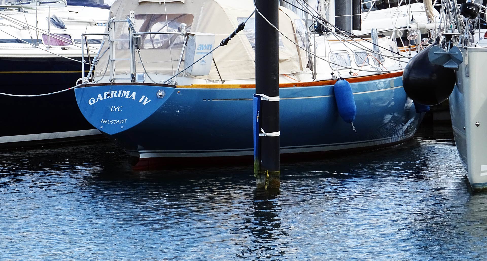
Although the magazines and marinas are full of flat designed, chined and wide-sterned modern yachts made to perform and host large volumes, a great number of yachts nowadays have their origins in the Seventies and Eighties as we call them “Classic GRP Yachts”. As I was roaming the jetties of my home marina I came to rest in front of such a very, very nice and well kept yacht: A German made Hanseat in blue.
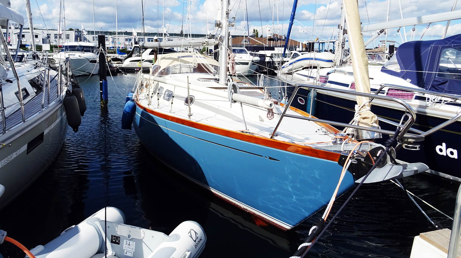
She bears the distinctive shape of a whole class of yachts which defined the Seventies yacht design: The IOR-yachts. IOR? Most of you may know this fictional conversation very well by their own neighbours in the berth: “Ah, this is a nice, classic boat indeed!”, “Yes, I like her. Her lines. She´s an IOR-yacht!”, “Yeah, for sure!”. IOR. We are all too familiar with the wide bulky hull shaped like a tea kettle. But what does IOR really mean? Here´s a short but hopefully clear explanation.
History of the IOR-Rating System
First of all, IOR, the “International Offshore Rule”, was a rating system introduced in the Sixties when for the first time in history regatta-rules and handicap ratings of Europe (namely of the Royal Ocean Racing Club of England, RORC) and America (to be precise of the CCA, the Cruising Club of America) sought to standardize their set of rules to ensure a worldwide rating system for sailing yacht races. The IOR has been kept in place up until the early Eighties when it was superseded by the more technical and scientific advanced IMS and IRC-rating, which are in place still today.
The set of rules changed massively during the years as their trustees tried to keep up with the pace of yacht designers and boat builders who sought to interpret the rules in such a way that thy would make the fastest boats possible within this set of rules. In such an environment, as we all know from other occasions, the mind of the people does incredible things and so the IOR set of rules sparked a whole generation of naval architects to create yachts and hull shapes within this set of rules – leading to this one, very iconic feature of IOR-yachts: The tea kettle shape of the hull. But what´s to it?
Design Features of Sailing Yachts under IOR-Rating
Well, in short, the IOR called for short waterline lengths. It favoured yachts with a short waterline and penalized longer boats. But as we all know: The longer the waterline length, the fast the boat sails. By the same time, naval architects and designers of the boats tried to keep the wetted surface of the yacht as small as possible, shortening the surface area of both hull, keel and rudder blades.

The yachts had been fitted with a sharp bow and the distinct “cruiser stern” which bears a large overhang. Now, let´s cast off and get the sails hoisted. What happens? First of all, when the IOR-shaped boat is now sailing, it will start to heel to leeward as expected. Due to the unique wide girth, the “tea kettle”-hull will now immerse into the water. As you may imagine by looking at such a tea kettle-shaped hull, due to the unique design features of the IOR-shaped hull, the length of the waterline increases greatly thus “imposing” a larger hull and increasing speed. That´s the theory.
Implications of IOR-designed Hulls
It really worked well for a number of yachts and IOR proved to be the offshore rule setting off a huge wave of new yachts to be built and new races to be raced. But the IOR-yachts had also some unwanted implications and sailing characteristics which are nowadays considered frowned upon the least if not to say dangerous.
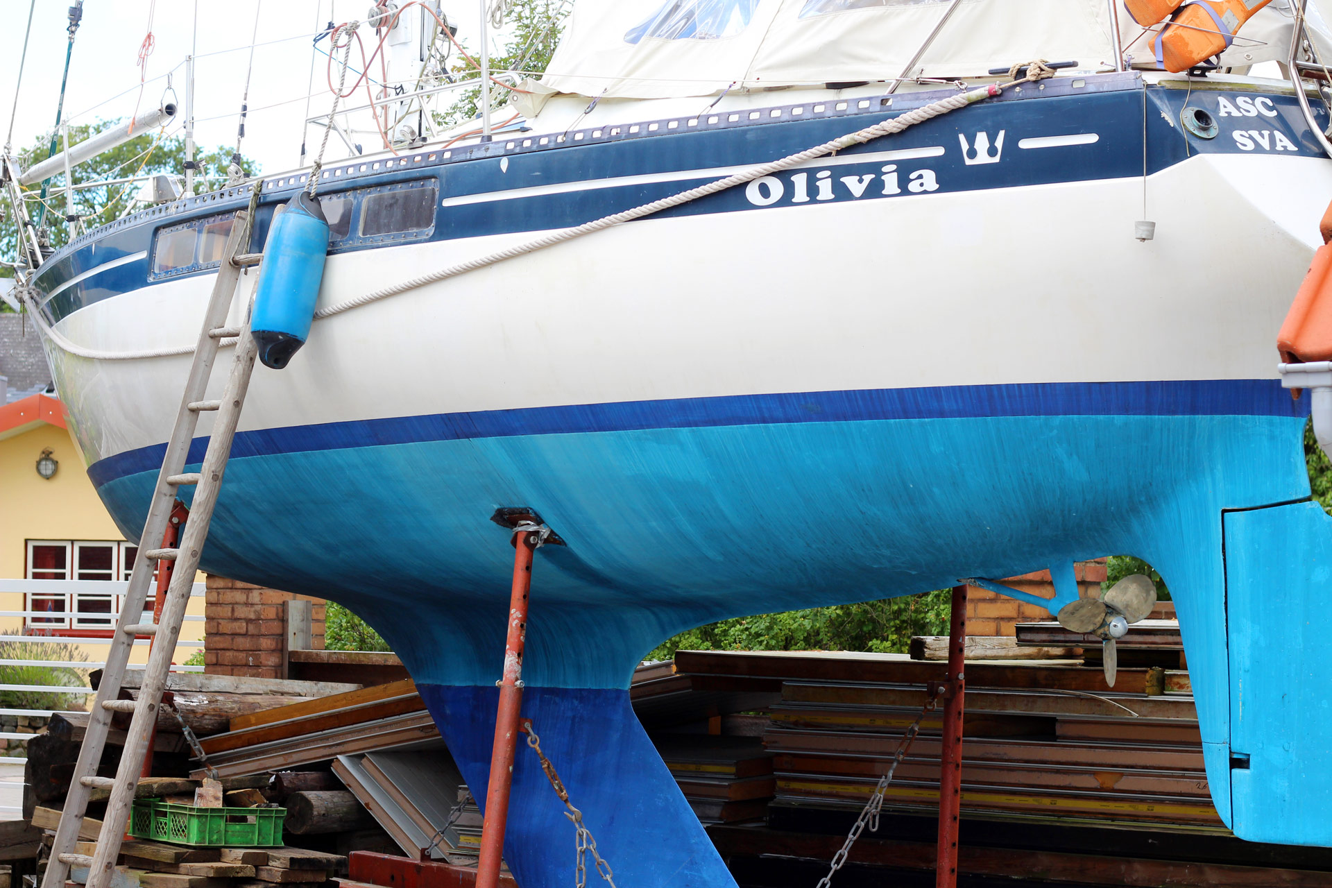
First of all, IOR-yachts are a kind of unstable boats in terms of seakindness. Due to the round chined hull and the wide girth, those boats are sailing massively heeled and are always in heavy motion even in lighter swell. Modern yachts with wider sterns and pronounced chines are heeling up to a certain point and will then sail very stable. Also, during the catastrophic events of the iconic Fastnet Race of 1979 more of those unwanted and possibly dangerous effects of IOR-constructions emerged in a way that the formula itself, its official role in regulating races and the design features had been abandoned by both the commissions as well as by the naval architects. If you want to dive deeper into this topic, there are numerous books and websites available.
In present naval design of yachts the IOR-inspired hull shapes have completely vanished. Although IOR-yachts have undeniable qualities in sailing hard upwind, they are nowadays considered too shaky in terms of sailing characteristics. Also, the somewhat narrow aft sections of these yachts do only leave space for quarter berths the best – best example here is the Beneteau FIRST 30 on which I did have the pleasure to make a 7-day-short dash to the Island of Bornholm (read the full articles here and here ). This yacht offered way more comfort and volume on 30 feet than my 33 feet IOR-era King´s Cruiser 33.
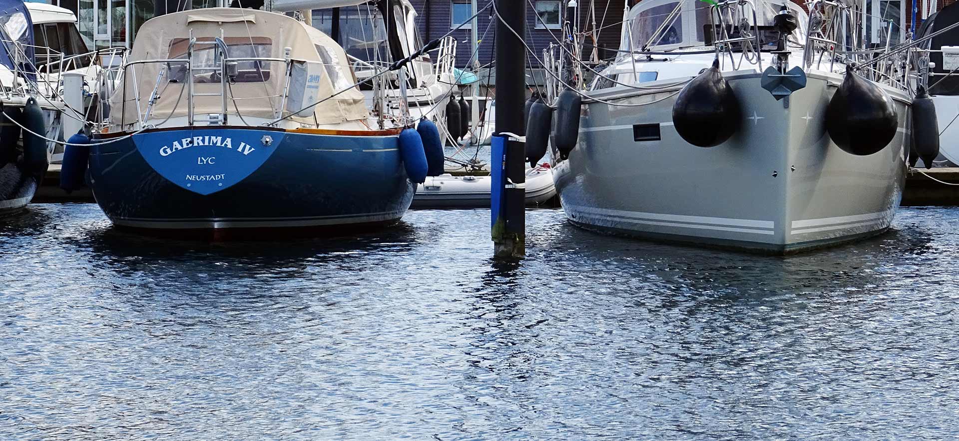
So in the end, the IOR-era was an attempt to flatten the worldwide rating systems to pave the way for a global racing circus. Designers reached out far to squeeze out the best designs possible. In a way the IOR proved that a bright mind can create miracles even inside the narrowest borders. But IOR also proved that too many rules can have limitations and even dangerous aspects as well. I personally admire some of the IOR-era designs, such as my own boat – but I also praise the technological advance that brought us faster, safer and beautiful designs as well.
Other interesting articles on that topic:
What´s the Yardstick rating system all about?
Tim Kroeger on racing the Swan 60 .
Sailing a Pogo 40 Racing Yacht.
Home » Rules of thumb for boat and yacht design – are they legitimate?
Rules of thumb for boat and yacht design – are they legitimate?
A creak of leather as he climbs on his hobby horse.
I sortof have a mission against using rules of thumb for boat, and particularly sailing boat design.
The problem is that often they have been stripped of the original context. A particular type of boat or a particular situation.
I haven’t really seen any that hold up in all situations – or at least very few.
Example 1 – Sail Area to Keel area
One rule of thumb that crawls around the net is that the centreboard area should be a particular proportion of the sail area. It is set up to work for yachts, but by the time you get down to small boats they travel so much slower that you need a lot of extra area.
My take is that for dinghies and other light boats (take that as missing context in the original) the centreboard or leeboard should be getting up toward 3ft deep and 10 inches wide.
If a boat carries a trapeze or leaning plank or is flared widely the area and probably depth will need to be tweaked up more the close you get to 16ft.
Inevitably if I write this often enough it will become a rule of thumb itself!
The risk is that the numbers will be presented as an absolute size as the contextualising information is gradually stripped away.
The original “rule of thumb” is even wrong for yachts. We know now that the depth of the centreboard, leeboard or keel is much more important than the area.
Example 2 – that you can stretch or shrink an existing boat by X%
One “rule of thumb” for boat design that continually comes up – and I got bitten by it once.
A customer asked for advice and someone gave him the impression it was OK.
This resulted in a boat that wouldn’t sail at all because it was too unstable and a customer unhappy with me.
A builder contacts me and says “something wrong with the boat” he built to my plan. Later I found that the 15.5ft Goat Island Skiff had been shrunk to 14ft. Article here .
That “rule of thumb” that is quoted is that you can generally shrink or expand a boat 10 or 15% with little problem. But this one is so wrong that it is a real danger.
15% reduction in overall dims and stability is halved.
The source often quoted for this is Bolger – who once said that a cargo boat could be increased in length by adding a 10 or 15% section in the middle. And with a possible improvement in fuel consumption.
Completely different statement. Not only is the body of a cargo boat mostly parallel sided in the middle, making the mod easier, but Bolger was tempering it with his vast experience.
He mentioned it only as a “notion” and certainly didn’t just add a bit in the middle. But drew it out carefully and properly as a new design.
Example 3 – the mast on the small boat should be three times the beam
Now for the Chappelle comment that mast length being 3 times the beam. Clearly he is talking about stability. So when he is talking about a specific model and size of boat he might be right … but what rig is he talking about – does he mean the peak/head of the sail? A lug sail could almost have double the area of a triangular sail under this “rule of thumb”.
These three boats have about the same mast length. The lug is 105 sq ft and the triangular sails are 82 sq ft.
But there is a more serious part to the argument.
In general if you double the size of the boat the stability goes up by a factor of 16. But the heeling forces go up by a factor of 8.
This is why a maxi yacht can either have a lighter keel – or like the modern ones be somewhat narrower than a smaller boat of roughly the same proportions – note the really long keels on model boats.
This pic shows a keel depth about half the length of the hull. The full size boat would need a keel 35ft (10m) deep – not necessary though
The best guide is looking at existing boats built to a similar purpose. Then identify which ones are good sailors and keeping to the same rough proportions.
Beyond that you can make sensible conclusions. Like an Oz Goose is more stable than a pointy nosed boat and put a bigger mast and sail in it. That is assuming it has a similar position of the centre of gravity.
Or that a new design will sail a little faster so maybe the centreboard can be made a little narrower.
Howard Chapelle knew exactly what he meant by the comment. But it has been pulled out of context by being turned into a “rule of thumb”.
Legitimate rules of thumb?
There are a couple of areas where I use rules of thumb.
Francis Herreshoff once said that the rake (angle back) of each mast on a boat needs to be 2 degrees more than the mast further forward. This is to simply prevent the masts look like their tips are converging. It is simple, it works and is not very open to interpretation. It also doesn’t have any effects beyond its brief.
Another place I use rules of thumb is in construction. For plywoods under 9mm an epoxy fillet needs to have a radius three times the plywood thickness. Same if you use a piece of timber in the join – the glue cleat needs to be have three times the gluing area to the ply of three times the ply thickness.
This is another rule that falls apart if taken too far. Testing shows that the fillet radius actually needs to be about 2.2 times the ply thickness. So there is a safety factor already applied (someone is always ready to “add a bit” for safety. Not necessary
But as the ply thickness increases the rule falls apart as you need to add glass cloth to get enough strength. And by that stage if you rely on fillets only then the fillet has so much volume that it has become crazy expensive.
So, I would suggest that rules of thumb are very useful for professional designers because they know the ramifications. It is easy for Bolger or Chapelle to know what they mean. AND know when the “rule” breaks down. But a better guide for amateur designers is to look closely at similar sized boats to see which ones perform well in terms of meeting the required use patterns. And which ones do not.
Cautions on copying current practice – beware of creep
A problem with looking at current practice as a standard is that it can go badly wrong if you just look in one place for information.
One example is plywood canoes and kayaks.
When I got into wooden boat building in the late 1980s it was common for a stitch and glue kayak to be built of 4mm (3/16″) ply and glass taped with 50mm (2″) tape inside and outside the seams.
This was also common for plywood racing dinghies in Australia and New Zealand. Which are subject to very much greater loads. This one is composite, but the sail area has slightly reduced over the years.
By 2000 the standard way was to use glass tape on the inside of the boat but outside of the boat in 4 or 6 oz (125 or 200gsm) glass cloth.
By 2010 several major manufacturers of kits are saying you have to build the boat with the boat completely sheathed with glass inside and out. As any builder knows – glassing the inside of a built hull is a cow of a job.
But it adds significantly to the expense, the cost and weight of the structure. Some say that glass has negligible weight – they obviously haven’t had to lug a boat very far!
Others say it is to get an “I-beam” or “composite sandwich” effect. This is misunderstanding how materials work. ALL materials loaded in bending, whether by having weight in the middle, or by water pressure work by the same method. It just has to be strong enough for purpose.
If you are expeditioning and doing rock shore landings it might be worth going to glass inside and outside. But this is not what 99% of users do.
An example of why most Kayak plans are overbuilt and overcomplicated …
One last parting shot … this is a Jarcat – a very clever range of trailer catamarans designed by Ross Turner in OZ. There are hundreds launched.
The Jarcats in the 16ft range is built of the same 4mm ply – with 20z glass on the outside only. A case of “creep”. A small step by step change which is not perceptible – but ends up a long way from the original point with little real justification.
Either the kayak designers or the Jarcat is right – the other wrong. With 500 or more Jarcats on the water …
I only found this out in the last couple of years.
Despite the Jarcat being around for a couple of dozen. My bad.
It has made me think that for most boats in dinghy size that are going to be glassed that some glass is more important than the actual weight per metre of the glass. Also think WHERE the glass is really needed.
Alternatively the earlier practice from the 60s and 70s might indicate that glass taping is all that is really needed. For most boats and most normal uses.
So it is sensible for amateur – and all designers – to look broadly and find out what is the actual best practice across a wide range of boats rather than accept things that are touted on the internet. Do your own research and share your conclusions.
Like this article! :-)
An article by the technical wizard Eric Sponberg regarding rules of thumb for boat design.
29 thoughts on “rules of thumb for boat and yacht design – are they legitimate”.
I agree and disagree with the rules of thumb position the author states. How committed to the rule are you in finanacial terms, and can you adjust and tune from there? is it an emergency? If you built a boat by rules of thumb and could tune it after the first few runs, you could get a real good boat, that fits your style. If you get dismasted how much sail do you need? broke the rudder? how big was it? how close to the rule of thumb does the deck plate swept oar you made in an emergency come to the rule? My drag racer back ground is all rules of thumbs then tune tune tune. If you jurry rigged a lee board by the rules of thumb then tuned it in practise before you made permanent mounts you would hace s good chance to build a hell of a boat.
Good points … you do need somewhere to start from. Whether it is to look at a boat (or drag racer) that is similar or search for some formula, equation or methodology.
Sometimes rules of thumb can work. And that’s why context is important.
The difficulty is that the “rules of thumb” are often used as a one shot method as a package solution.
But if there is a tuner/tinkerer’s culture like drag racing it can be a very successful method.
However, most boats are built just to use and not to worry about.
And I’m sure in the drag racing world there are lots of people who have read a bit … and then those who actually have been committed for a long time and actually gone up the practical learning curve of actually competing and seeing how the ideas pan out.
The first group are not so useful. But the guys up the real learning curve who have tested the rules of thumb and found them worthy .. or unworthy .. their words are like gold.
The only rule of thumb I cling to religiously is that when someone starts flinging around ‘rules of thumb’ too casually, he gets beaten with a stick no bigger than my thumb.
Seriously, though, this is a great discussion! As a designer of things wooden, I find some of my most exciting failures and successes come from challenging my own developed-over-time patterns and assumptions. “Hmmmmm…. it’s probably crazy, but I wonder what would happen if I ignored reason and…”
Too much modern stuff — should be a discussion on “rule of digital calculator”….
The penny (size) of a nail used to fasten a plank on a wooden boat is one penny for every eight of an inch of thickness of the plank. For softwoods, add two pennies.
The general rule for lower mast diameter was 7/8 inch for every foot of beam.
Beveling for caulking: the outer edge should be beveled 1/16 for every inch of plank thickness; beveling from the center of the plank.
https://web.archive.org/web/20151025144750/http://www.tsca.net:80/CRBB/thumb.htm
Thanks for the comment.
I can only agree. Like PAR says above, that going straight in and grabbing the pocket calculator and thinking it is going to work is a mistake.
I use computers for my design work, but really, it is only for the laying out of the lines and doing the calculations. You still need to know what the results of the calculations mean! :)
Similar with rules of thumb. The middle one is probably correct for a certain type of boat the builder was used to building, but will fall apart for different types of boats. For example a light dinghy 5 ft wide and 13 ft long compared to a classic square metre style yacht which might be about 30ft or longer on the same beam. But kept within its original intention of size and type it probably performs admirably.
I rather tend to trust constructional rules like your other two, but usually do check them against the result from more modern standards. Maybe not all that modern if we are talking about rivets – maybe I mean I will check a couple of other sources just to make sure I’m not overdoing or underdoing it.
The first couple of boats I designed were laid out full size on the floor. Because that’s the way I had been building them until that point. As I got used to computer design tools I understood very clearly that it really is the same process as drawing on the floor, except the calculation results are available more quickly and more accurately.
The computer model has to come back to wood at some point – so if you try to make the lines on the computer do something that wood won’t do when the boat is actually built, it will turn around and bite you quite badly.
This is probably a good thing.
For what it’s worth Mik, I keep my rules of thumb to myself, if for no other reason, then to prevent it from becoming a generally accepted rule of thumb. In reality, I keep it because I can use this information to advantage.
For the most part we’re in agreement in that these rules of thumb are worthless, for the novice sailor or budding designer and can cause much more harm then good, if considered more then what they are, which is a very rough and general guide, typically for comparative uses.
I have a secret rule of thumb for finding a wife, but it’s use hasn’t worked well for others, for their lack of understanding of it’s implementation.
Most of us in the industry, use rules of thumb without thinking about them. By this I simply mean we’ve developed such a sense of proportion and understanding about the way things work, that we can guesstimate fairly closely what a prospective boat’s displacement might need to be, to meet the SOR, general hull form shapes, approximate sail area necessary for the preformance envelope envisioned, etc., etc., etc. This is using the rules of thumb, possably on a subconscious level to a degree, as I for one don’t think about it, I just know or have a feel for what’s right, before I run the math. It’s rare for me to be surprised by the “numbers”
Another example would be a fast daysailor I did not too long ago. She was a narrow V bottom boat, with a fairly flat chine, so she’d be good up wind, if you can hold her down and have less leeward bow wave resistance, then a hull with a dramatic chine sweep at the bow. This naturally meant the sail area would be somewhat less then the ideals for a fast dayboat. So a moderate WS/SA and SA/D are the result. Just looking at these to figures you’d think she wasn’t particularly impressive, but having sailed the prototype at over 16 knots, this isn’t the case. She does all the things I expected, including pound hard going to windward, because of the flat chine choice (see, I didn’t say compromise, even though you know it was).
Most of the “rules” are as Mik suggests and just a general guide to compare against other, similarly sized craft. Once you generate some experience and more importantly success with design, you harbor favorites, a keenness for certain things and an understanding of the “relationships” with the “numbers”. These become second nature after a while, as you build on successes and learn from not so successful attempts. This understanding then becomes a set of personal rules of thumb. You may wish to test or stretch the rules from time to time, but most of the designs you work on, will usually fall right inside the comfort zone your personal rules create.
Completely agree Paul,
The first para in my article talks about the “context” of the rule of thumb. We all have shortcuts as designers.
The risk is when the “rule of thumb” loses its original context.
As designers we have some experience to back up our use of rules of thumb. Often because we have the chance to make mistakes – usually of the smaller kind – like the centreboard on my original BETH sailing canoe being too small. Handling could only be describes as lazy and performance disappointing upwind. I made another board with 9″ more depth and she became pretty good upwind – not quite good enough to stay with a well sailed Laser, but not embarrassingly far off the pace either.
Or sometimes further experience can show us that the rule of thumb is just wrong. Like the excessive glass recommended for kayaks one or the “you can shrink or expand a boat 10 or 15% with few problems” one.
Though it is hard to know if these are wrong because of a change of context or loss of context.
But I would generally think, that if a simply stated rule of thumb appears to be applied universally then it is highly suspect.
Also a good rule of thumb is if something is made heavier and stronger over the years … then it is very probably being overbuilt or overdesigned.
In other words there needs to be a realistic justification for it, rather than some sort of nebulous “creep”
Thanks again!
Hi Mik, I use rules of thumb all the time, but generally I don’t think they are understood by the budding or would be designer.
A good example of this is a custom design I recently started. It’s not a modern boat, but a “in the spirit of” type of design and a cruiser of about 26′ (7.9 m). In this vain I knew I wanted an SA/D in the 16 to 18 range, but since he would likely spend time in the trades occasionally, I elected to be on the low end of this rule of thumb for a cruiser. She carries a 15.7 SA/D, but has light air hoist options to jack this up to 25 if desired.
For comfort I elected to go after a moderate D/L, but also to help preformance I stayed on the low side of the rule of thumb and she ended up as a 266 D/L.
The amount of sail area rule of thumb, based on wetted surface supplies well and under working sails she’s a 2.2, again in keeping with her cruiser status, though under light air sails, this is a much more respectable 2.6, so she’ll fair very well in soft wind strengths.
As far as the 3 times the beam thing, well this is as absurd as you make it in your piece, but maybe it once had some value. We are also in complete agreement when it comes to scaling up or down a particular design. In fact, this is a very common request for a designer. “Hey, can I have this boat, just 20% longer?” My reply is much like yours and a quickly uttered “nope”.
As far as keel area, well I didn’t have a problem here as she’s a full keeled boat, though the forefoot is well cut back, partly to optimize the appendage for the rig choices, but mostly to get her to maneuver smartly. Her skeg hung rudder, does fall within the usual rule of thumb for selecting it’s area, but I didn’t use it as a guide. I had only so much room left under her after the sail drive leg, so I filled most of what’s left with the skeg and rudder assembly, of course with sufficient enough separation to make the skeg useful.
I guess my point is, rules of thumb can be very handy, particularly in the conceptual stages of the design spiral. The important thing is knowing how and when to employ them. For the most part they are useless in all but the beginning of the design stages, more a ball park type of thing.
Telling someone they should shoot for a 2.45 wetted surface to sail area ratio is meaningless, unless you know what this will bring to the other perimeters and particulars of the design. For example (again) this WS/SA ratio would be too “tall” on a narrow, slack bilged craft or grossly under canvased on a canoe body with fat hind quarters. You have to know where, how and when the apply and most importantly their limitations and/or implications to the rest of the project.
Rules of thumb don’t govern the design, but do establish general set of target ranges to shoot at while working up the design ladder.
Howdy Paul,
Nice comments!
I think there is a difference between analysis and “rules of thumb”. But maybe I am clutching at straws?!
The ratios of displacement to length or Sail Area to Displacement are a progressive estimate to break boats into different classes of behaviour. We know what the numbers should look like for a slow and steady cruiser compared to a mad planing machine and the “cruiser racers and occasional offshore surfers fit between and have their own ranges.
Those types of analysis ARE very useful because they come from real analysis.
But simple single statements that are supposed to fit all cases are highly suspect. Like “the area of the centreboard or keel should be 4% of the sail area”.
The best resource of both good rules of thumb and “stoopid” ones is Gavin Atkin’s page on The Rules (of boat design) .
Gavin has collected a whole heap of them, but I would like to throw away quite a few as complete nonsense and almost completely misleading. Each one is a great starting point for a discussion though – or a talk about boat design. Just to pick out where each is a supportable statement and where it starts falling apart – some sooner than others!
Some would do this because they are taken out of their original context. Also Gavin has juxtaposed the contradictory ones.
But the ones that try to be a single simple solution are the most suspect.
“The beam of a flat bottomed boat should be no more than half the length; if it is to be rowed or sailed, the length should be two and a half to three times the beam – HV Sucher”
The list is huge FUN though and lead to other thoughts – which is exactly why Gavin posted them – note his quote at the top from Norman Skene – it is an obvious disclaimer to those who read between (analyse) the lines rather than trust the lines themselves (repeat without thinking)!
Thanks for posting!
What I should have added, to bring the post back to topic, is that all the stuff I can find out about small-craft design (and I’ve been lucky enough to talk to most of the top names) could be encapsulated in one rule of thumb that there is no one type (and “type” includes nationality) of craft that is much more efficient than the others – if you define “efficiency” as including aspects such as cost, ease of use, versatility, etc.
Howdy Chris,
I guess what I was getting at was that there are boats that can sail very well through all conditions – up and beyond the speeds of comparable boats.
When the 505 came out, it was one kind of revolution, the Tornado another. 50 years after their design these are still very close to the best standard in terms of all round performance – they have been overtaken, but not by that much!
Just as a comparison, the International Canoe, pre spinnaker was screamingly fast in some conditions, well able to burn off a 505 – but in other conditions it sails just like a standard sailing dinghy with 10sq metres of sail.
I guess that this also disqualifies my thesis about the moths! And sailboards – at least if you take one type of sailboard at a time.
But the wind speed for Moth effectiveness moves ever downwards. It must have a limit of course – there will always be a windspeed where a foiler moth becomes about as much fun as sailing a wet sock.
Thanks very much for the roundup of sailboard performance – especially the comments of bigger sails set up for better handling. When the first 7.5 sails started appearing with this thinking, I thought it might be the start of a single rig that would do for all conditions.
I agree completely and in heartfelt way with out about backyarders being slowly eliminated. With two or three main manufacturers of foiler Moths we won’t see the fast development and ability to drop blind lines of development that existed in the days of homebuilding Moths when 8 or 12 smart guys in Sydney would build new boats over each winter. Not to mention the ones in the UK. Or same for the early days of sailboards – you remember those somewhat lumpy styrene cored kevlar and epoxy creations of the ’70s? Lots of smart guys involved there too.
Pity that they decided to put a minimum wind limit in for international raceboard events. That’s the sort of rule that is often counterproductive to developing better boards. Or like allowing canting keeled yachts that have to run engines – it means that develoopment of more sensible alternatives is not supported.
Thanks for replying, Mike.
I suppose part of the issue is defining “efficiency”. Yes, we both agreed that boards are not as efficient (in some respects) as a foiler Moth. However, as compared to a non-foiling dinghy and when compared against dinghies of similar LOA or sail area, the boards are certainly efficient, as demonstrated by their superior all-round speed over the pre-foiling Moths which were arguably the most efficient dinghy of their day.
Board development has been stifled by rules, IMHO. Not that I’m against rules, but there’s no really open class left in boards. All the International classes are restricted to production boards and a certain minimum run is required. So backyarders of the type that produced foiler Moths and the original windsurfer are ruled out of the sport, which is bizarre IMHO.
The Formula Windsurfing boards are producing excellent performance, comparable to a foiler Moth when both are planing or foiling, but FW boards are very short and fat and basically cannot finish a race under about 8 knots of wind. I’d rate them therefore less efficient and slower all-round than a foiler Moth. Dimensionally, the FW board has 50% more sail but about 60% of the LOA and cost.
The Division II boards are basically dead (the class has gone and they are ruled out of other classes) but remain the fastest under about 8 knots and, according to some experts a few years ago, the fastest around a course from 0 to 30 knots because of their light-wind prowess (going as fast as a Canoe or pre-foil Moth in light winds with 7.4m of sail on a restricted platform is pretty damn outstanding, especially when you move away from the latter two in more breeze).
The advent of larger sails has improved the performance of Raceboards although the new boards (there are now three in production, a big improvement over earlier years) are basically no faster than Mistral Equipe IIs and other 1990s boards.
The larger sails may be easier to handle because of superior materials and design that has sacrificed lift per metre for superior handling. Of course, while that allows you to carry a bigger rig, it also means you have to lug that bigger rig through transitions and pay for the bigger sail and spars…. sometimes I think we over-rate the superior performance of modern flatter sails. Interestingly while windsurfer talk about light modern rigs, most sails are at least twice as heavy as the Windsurfer One Design mylar sail and the old-fashioned One Design sail appears to generate much more lift per metre.
The righting moment issue has been attacked in Formula and shortboards by making them wider, with Formula boards hitting the class beam limit of 1m. That allows them to carry huge rigs and fins. However, in sub-planing conditions the very high drag makes these boards extremely slow.
A skinny longboard with hiking racks could be a real mover, but since the longboards can already beat any comparable single-sail single-handed non-foiling dinghy you could say that speed is not the issue. Merely adding more RM would not get them to the pace of a foiler Moth around a WW/LW course,as far as I can tell. A foiling longboard would be an interesting beast!
The yardsticks are at the bottom of the on-line VYC listing but they have the Div 2 boards listed incorrectly.
There’s only one Raceboard fleet in Sydney (Dobroyd on Iron Cove) and one in Wollongong, with a small scattering in other states.
BTW on general dinghy design (as discussed above) I’m not sure that ANZAC design has lead the way as much as is often assumed. For example, the National 12 was miles ahead of Australian designs in adopting the U sections seen in most high-performance modern craft. We haven’t had a world’s winning design in 14s, for example, since the Northern Hemisphere and Aussie classes were unified. The mylar-sailed Tasar now seems to be pretty much back on a par with the NS14 in terms of pace (judging from the last two regattas where significant fleets raced) yet the National 12 apparently regularly beats Tasars in UK conditions despite being almost 3′ shorter.
As always, Mike, you write with a great deal of knowledge about small boat design. However, I would like to provide some input about windsurfer efficiency.
Seen in the same terms as a non-foiling dinghy – i.e. their all-round speed around a conventional course in a range of winds – the boards are definitely efficient for their LOA and SA. There are actually yardsticks that are pretty reliable. They rate the Raceboards (3.9m, around 9.5m of sail) at a similar pace to the International Canoe (5.3m-ish, 10m of sail) and from about 8 knots that’s under-rating the pace of the board. In 10-12 knots or so the board is toasting the IC upwind and downwind.
Similarly, the Division 2 boards (3.9m, 7.4m sails) out-paced the pre-foil International Moths which had fewer rule restrictions. I don’t believe the extra length of the round-bottomed D2 boards was a significant factor as D2 design had moved away from maximising LWL. From about 8 knots the board was considerably faster,from my racing against the world’s best 2 Moths, and again the board is quicker than the Canoe from around 8-12 knots.
While these speed are definitely not in the realm of the foilers, they are notably quicker than the best of the conventional boats of similar dimensions. Just a minor point but you are so accurate on this stuff I thought I’d mention it.
Grrrr, I hate to be wrong, but I’m glad for the correction.
In a way, my numbers, taken from the yardsticks below agree completely with what you say – so don’t think I was too far out – but certainly my EMPHASIS was out!
My big sin was, I think this
The thing about the moths is their EFFICIENCY. Sailboards are not even close.
If the sailboards are being compared with the pre-spinnaker international canoes – then I think there is some validity in what I say. The canoes are brilliant boats upwind and reaching, but on turning onto the running leg in light or medium weather also became nothing special – just another dinghy. So to compare the sailboard probably admits there are some holes in its performance too. Whatever the canoe or the sailboard might do in the right conditions to a more complex but fast boat like a 505.
Are the yardsticks reflecting this available, I looked everywhere!
I did a check on your email address and found activity on the Taser IC and sailboard furums. Useful thing Google!
Of the sailboard class with the best performance, what is the basic configuration these days? Volume, width, board weight
Are centreboards still used on raceboards?
Also where are the competitive Raceboards fleets around Sydney these days?
Follow up – I had a good look around to see what has happened with sailboard design. It seems that it has largely stagnated with boards like the Lechner and the D2s being quoted as being reasonable examples. The big developments that have been made have been with sail design – with boards being able to carry 9.5m sails through to surprisingly high windstrengths, when I remember a decade or more ago that they were struggling to carry 7.5 square metre sails.
It might be fair to say that my assumptions, partially drawn from Bethwaite is that the sailboards have been too limited by a lack of righting moment (no trapeze, leaning planks or stilts!) have been overcome to some extent as evidenced by the bigger sails. Though I haven’t read the revised version of his book “High Speed Sailing” since the first editions.
Well, as far as them going around the harbor at 25 knots, it couldn’t be worse than the jetskis at 50 knots ;)
Actually I have thought at times about taking one of the square boats like the Oz Racer or the Goose and adding foils. Those nice square corners just cry out as attachment points for foils…..
Of course to complicate matters, I would want to make foils that are tubular much like ducted fans but no mechanicals. Either that or the ladder foils that loose lift as they emerge to focus on stability rather than speed.
Haha – any mindless fool can BUZZ BUZZ around the harbour on a jetski – but when it comes to it – they drive similarly enough to a car with some sideslip. But a sailing boat – I can imagine someone thinking they can blast across in front of a Manly Ferry, not realising that they are gradually pinching the boat and find they are dead stopped in front of the Ferry. Or cannoning into another boat when a gust hits.
The thing about foiling is that every contrivance will crash to earth occasionall. With the big flat area of the PDR I would recommend getting your foiling photos early in the piece incase of a fatal crash later. Fatal to the big flat sections of the PDR!
The ladder foils would be more tolerant as there is more that has to ventilate for you to lose lift completely – whereas when the T foils suck air down from the surface they just lose the lot.
Doesn’t seem to worry the moths too much – before the foils they would sail happily at 15 knots or so – which is very fast for a monohull. A PDR hull might be a bit at sixes and sevens hitting the water at that type of speed!
I think you could go broke trying to sell reef points in OZ.
Maybe some day they will make something with lifting foils for us old folks just to make for a nice smooth ride instead of banging into chop.
Haha – we are an embarrassing lot really!
That’s the reason we put so much sail on the OzRacer/OzPDRacer – as a sort of antipodean joke.
And were we surprised when we found the boats had enough stability to carry it easily!
I think there is space in the market for something simple to sail but foiling. The company that makes the ’49er class dinghy, Starboard Products, has produced some very fast experimental boats, but they have been worried about putting them on the marketplace because they are not sure that having inexperienced sailors zooting around the harbour at 25 knots is such a great idea!
Your point about bangin’ into chop is a great one. Have a look on youtube at some of the big multihulls going fast in a seaway and then compare to Hyroptere – the similarly sized foil tri – it looks as smooth as silk in comparison – though every one is on edge.
Well, before this thread gets too long…
In general, I get the feeling that you enjoy the open class developments. The experimental stuff that may be a huge step forward or a non-starter but still a valiant effort.
I’m quite sure that when the first Moths started flying, they were just a strange oddity until they got everything sorted out. But one huge difference is that they continue while the other foilers such Hobie Tri-Foiler and the Windrider Rave just make a curious historical footnote. Do you think that the closed nature of just being a pre-packaged solution and not open to tinkering killed them off or just the fact that they were too expensive to get adopted on a larger scale?
Is it that someone gets a good start but without the gestalt of other people picking and improving, it stagnates?
Why do you think that some designs fall flat? A perfect example in my opinion is the Adventure Trimaran 24. I look at this video
http://www.youtube.com/watch?v=echGgGtE424
and see it as just stunning as it ghosts along. But in the other videos out in real wind in pretty modest sailing conditions, it does fine but nothing to particularly commend it over any of the other multi-hulls.
Very well observed David – and I have no fear of this discussion getting too long – it is great.
The Moth has moved a bit away from its roots. It was a constructor’s class until recently with teams of expert and less expert builders making boats in the off season out of sticks and glue.
It has few restriction. Hull Length 11ft Sail area 85sq ft (sorry – I am not metric with sail areas) Maximum height of sail above deck – 18ft No hollows in the hull shape (to prevent catamarans) No minimum weight, minimum beam
During those days the moths were very potent for their cost and size.
The scow moths of Oz – this one was the only one in the 2011 worlds in Oz – and is just stooging around before the start – it is a late ’70s design, before the transoms went narrower for better downwind control (mentioned in the comments above).
And the skiff moths of the UK (nonfoiling at that stage) – the pici is of John Claridge – one of the guys who made the skiff moths very competitive with the Australian Scows (finally).
… fought it out for dominance for decades – and resulted in the most sophisticated lighweight construction – 0.7mm (1/64″) hull skins and bulkheads and the cockpit out of 1.2mm with very light glass under. This was aircraft type construction – true monocoque skin supported by light western red cedar stringers.
Not for everyone either – but it showed what is possible. The scow hulls were about 34lbs without fittings. They ended up with a performance yardstick similar to the International Contender – 50% longer and 50% more sail.
This is the Contender – a puny 11ft boat can sail equal with that – it is pretty similar to the Paper Jet we discussed earlier in term of hullshape technology. Don’t get me wrong – the Contender is way fun to sail too.
A triumph of efficiency over sail area and length.
In the end the skiffs went really narrow – and that’s when they started to become superior to the scows. They tended to nosedive though – so inverted T foils were put on the rudder – so when the boat goes nose down the forces developed by the rudder T foil pull the stern down so the boat stays in trim automatically.
The next step was the trifoiler – think Hobie Trifoiler but with the weight and complication and expense wrung out. The minimal approach really defines the Moth.
Hobie trifoiler followed by a trifoil moth pic
That was the mistake of the Hobie trifoiler – it was big, complex and expensive. The little trifoiler moths were quite easy to sail (apart from the occasional crash off the foils) and represented a rooftop package weighing little more than 90lbs all up. However they were considered too easy to sail. Suddenly a class that was considered to put a premium on handling and skill could be sailed by geriatrics. They were in a quandary.
One of the main drivers of the DIY wooden moth development was a Sydneysider – Ian Ward. He demonstrated a bifoiler (two foils only) after being told it was “impossible to balance” – two foils only concept – was possible to sail by parading up and down in front of the sailors at the Seaforth Moth Club (I think that is the story). The foilers are easier to sail than the non foiled narrow moths, but very difficult to sail well.
Originally the hydrofoil moths would race amongst the conventional boats at the worlds – would win one or two races by miles but the rest of the time not look very special. This is exactly had happened when the very narrow skiff moths were developed too (in the UK). The first generation bicycle configuration Moths would only fly reliably in 10 knots of breeze.
I saw some racing from a distance at the beginning and you would see one of the few foilers jump out of the water and disappear into the distance, then drop back into the water and the other boats would catch up.
But week in, week out racing has changed all that. They now fly in quite light breezes – about 5 knots of breeze. This is not HALF of 10 knots – the power available in a 5 knot breeze is only 1/4 of that in 10 – showing how far the boats have come. All sailors gybe without falling off the foils and some of the better sailors can tack without falling off too.
So to the trifoiler (and windrider) – it was too big, too heavy, too complicated to rig and unrig and very expensive. The complexity led to unreliability of the structure. How could it succeed? However it pointed the way. I was gobsmacked to see one on TV just turning circle after circle. Prior to this hydrofoils (apart from the little speed week cat “Mayfly” – another important step) were touchy and difficult – But Russell Long brought something new into creation – you could sail in circles all day and anyone could sail it. But every step of production added more and more complexity.
You need some pressures applied externally to be minimal – the moths are restricted by maximum sail area (it is not big) and no minimum weight – so huge pressures to simplify.
The pressure on the Moths from the start has been to do things in the simplest, most minimal way – you just need to look at the fittings on the boats to see that. Bits are “lashed on” with carbon roving soaked in epoxy. They have lost the low cost of the wood boats – but some of that thinking still holds on – but I think they are still justified because of the almost harrowing speed of development.
Here is a brochure for a 420 dinghy – a standard fibreglass racing dinghy used for international competition. It is great for regattas, but its performance is a bit “old hat”. The full price to get one on the water is similar to the cost of the Moth – $16K compared to $18K. I know which one I would have been sailing at that stage of my career.
They start looking a bit sick when you realise that wooden moths could be built for about $2000 now – still very fast boats for their size.
I do regret the “build a boat during winter” approach has been lost – the loss of that might mean that Moths head for more and more expense, rather than just costing a plywood, epoxy and timber budget – and 35lbs of that doesn’t cost much. So far they are reasonably priced as a full carbon production thing compared to boats of similar performance and many of much less performance. – but that will tend to stagnate development – instead of 20 home builders creating slightly different boats, we have to wait for two or three manufacturers to do some development.
Moths would have been impossible without “Mayfly” or the “Trifoiler” so give credit where credit is due. But the open-ness of the class and the rule pressures to make things minimal have been a potent cocktail to make Moths the amazing boats they are.
photo sets on Flickr
And here is the Moth’s own viewpoint of their development
Michael, Could you provide or tell me where to find some more information on the trifoiler Moth? I am very interested in constructing one as it seems much simpler to construct and sail than a “normal” foiling Moth.
I would make enquiries of the Moth Association in Australia to see if they can direct you to someone who can give you some information.
They also have a good website and some of the state websites and their old website has considerable information … maybe you can join their chat forum (ask them) and see if anyone has info they can share.
I am pretty sure most of the trifoiler development was manufactured stuff. I don’t know if there might even be some parts for sale.
Main thing is that whatever it is attached to has to be pretty light – I think Moths were around 80lbs all up in that era, and also a fairly fast intrinsic hullshape so that when you crash off the foils the hull can kinda keep on sailing.
http://www.moth.asn.au/
HOpe this helps Michael.
I am curious though. I wonder how the total weight of the mast and standing rigging is compares to a free standing rig. I realize that these Moths are under a different set of constraints (and not designed for all around sailing.) They are cool in their own technologically interesting way but pretty much just an obscure offshoot much like hovercraft.
You can get one person moving faster across the water with a wind surfer or a sail board and not spend 18K. I think that what you make with your high performance boats such as GIS (although it is cunningly disguised as a “Traditional Boat”) makes a lot more sense. Lower cost barrier for entry. Sails in a wider range of conditions. Doubles as a party boat when you put more people aboard.
I think much more interesting than the Moths are the little PaperJet 14 from Dudly Dix ( http://www.dixdesign.com/paperjet.htm ) The three rig options make it something you can grow with or play with different groups. I know there are others in that genre but these are cheap and readily available. Under 1K in kit form is much more reasonable than the 18K for the Moths. Could possibly have it on the water under 3K.
I still think the GIS is a nicer option since you can also carry people and not just a 1-person toy. Not to mention simpler rigging.
Howdy David,
The Paperjet is a fine little boat, but it doesn’t do anything particularly new. It represents something similar to the plywood boats in OZ from about the 1980 era – though the Paperjet construction method is much, much better sorted out. I would still recommend it as a boat to consider for many sailors.
Since that time there have been very big discoveries about what makes small boats fast but easy to handle. Starting from the mid 1980s in the Moth class where they found the scow type would eliminate nosediving if they made drastic changes to the shape of the stern – before that they thought they had to do something at the BOW to stop it from digging in. This happens to be true for multihulls as well – adjust the back half of the boat and you can prevent much nosediving.
It is the same reason canoe sterned boats have a better reputation for seaworthiness – about distribution of hull volume, rocker (and in a yacht the aft buttock lines.
From the scow moths it went to the skiffs and then restricted classes like the NS14 and Cherub. The Goat incorporates that thinking and it can heel to very high angles and still steer reliably – something the pre 1980 hullforms won’t do.
A second area is planing behaviour – the experience of these new hullshapes can be a surprised to very experienced sailors (unless they are sailing an Oz or NZ derived design like the Olympic 49er. This is from Michael McNamara who makes sails for some of the most competitive classes in the UK about sailing the Goat. This is what he wrote to Ralph Gersson in the Netherlands.
I had a nice long sail in Richard`s Goat Island Skiff today and had a lovely sail. He has made a great job of the boat and it went like a dream. I was very impressed with how simple the controls were and how quickly the boat went. It was also beautifully balanced . As you could expect the boat felt better when it was slightly heeled when beating. Off wind it felt fast but didn’t create a planing sort of wash…it just went faster and faster . When tacking I found that I had to be quite forceful in pushing it into the wind and it was definitely better to “roll” it coming out of the tack.
The highlighted words are exactly what has been worked on in OZ – playing with rocker, volume distribution and effective hull bottom width.. Looking at the way the National 12s are sailing in the UK – they are using the same methods and it is spreading to other classes where there is freedom to change the hull shape. Interestingly the big high speed yachts like the supermaxis and Open60s are still oblivious to how much better their boats could be. You can keep up higher speeds in marginal planing conditions because the boat transitions through to planing much more easily and you can push closer to the edge and know you can keep control with much less rudder effort.
OK – Moths.
Years ago on Sydney Harbour they had a race between C-class Catamarans (the full wing Miss Nylex), Tornados and 18ft skiffs. The C-class cat came first, the 18ft skiffs came second and the Tornados were shocked to find that they came third.
A sailboard would not be in the hunt because their upwind performance is so poor and their dead downwind performance requires much longer distances than the others. The others can go deep. On a reach a sailboard comes into its own, but upwind and down or in rough water they are nothing special. Actually, I exaggerate – they ARE special, but are let down by performance in particular areas.
I agree partially with your argument about cost – but by the time you put a sailboard together with the different rigs and accessories it is going to be a good proportion of the $18K for a Moth. And its never certain whether you need the longboard or a high volume shortboard for light winds or if you need the low volume shortboard for over 10 knots. Might end up being much more expensive than the Moth if a sailboard sailor is looking for best performance in all winds.
I will back this up with data.
So lets look at performance of a few boats around a regular racecourse. The Portsmouth Yardstick is based on actual performances averaged around real racecourses using real boats. Check the current Portsmouth yardsticks (PDF) (note the Moth has two figures – foiling and non foiling versions)
Tornado – two person catamaran – 20ft – 643 A-class cat – 1 person singlehanded – 18ft – 690 (very highly developed because of a lack of restrictions in design) Hobie 16 – two person beach cat – 802 505 – International trapeze racing dinghy – 16ft – 902
There is no official number for the sailboards I could find, but from pursuit races in the UK the sailboard people themselves were giving numbers close to the 505 – which is pretty good – perhaps a little optimistic, but let’s accept their figure… Raceboard class – 902 approx
Moth – 690 This is a serious breakthrough – around a course 30% faster than the best normal dinghies and sailboards and equal with the best singlehanded cats.
A sailboard can go faster in a 50ft wide trench down in the tropics with wind from the perfect direction – but put the same board on an upwind downwind course in a normal chop and it won’t be able to get to the top mark – too specialised with a narrow band of efficiency. Moths have full sailing performance with efficiency on all points of sail. Even non foiling they have close to the upwind speed of the Goat Island Skiff, sailed hard and 4.5ft longer.
I agree the particular solution is not for everyone!
In some ways it is still early days for Moths – but the intensity of the racing (over 100 boats at the worlds) will probably mean more big jumps – extending the takeoff speed ever downwards and reducing the “crash and burn” in really rough water. The price at about half of a high performance two person dinghy has meant a serious growth in the fleet and the countries sailing. Ten years ago there would have never have been participants in the Moth from the USA, China, Sweden.
It really is a big jump in many ways. But as you say – not for everyone!
Best wishes Michael
I think the biggest problem to using these kinds of rules of thumb has been over specialization. You have three competing goals that have to balance out: the Designer, the Engineer, and the Builder. Each of them off isolation make bad decisions for the others. In a modern context, they are all different people and may not even normally work together. The Herreshoffs are a perfect example of when it worked well. They were a one stop shop. You got the designers, the engineers, and the builders in one package that all worked together and understood their roles and were able to accommodate each other.
The Engineer wants to build in more and more reliability and the overall design and build considerations are secondary. They want to calculate everything, whether it can even be calculated or not, and are resistant to making extraordinary leaps by deviating from standard practice.
The Designer wants to make their ideas real. Let the other people do all the real calculations and figure out how to make it. There is a lot of “eventually the technology will be available.”
The Builder is looking at cost and how to actually put things together. They know what the materials really cost and understand the reality of what the materials can do in a practical sense rather than a theoretically.
In the limited context of boat building, the Engineer is in trouble. The environment is dynamic and chaotic. Only recently with high performance computing has it even been thinkable to try to accurately model what forces are involved even in one static scenario let alone in all conditions. Sometimes all they can do is make a guess and see what has worked before and maybe try some tiny deviation.
The Designer always has the handicap that they are trying to divine what the customer wants and it can end up being akin to working with an Ouija board. They tend to follow what everyone else is doing. Kinda like the car designers putting fins on cars.
The Builder is constantly confronted with new materials that they do not yet understand and the rest of the materials are full of flaws and variations. Many of the newest materials are so unknown that about all you have to go on is the advertising copy from the manufacturer and they are afraid to put down hard information because they think everyone will sue them. They also get the blame with things go wrong. The Designers and Engineers just fold their arms over their chest and say they were right and the Builder just didn’t follow their specifications.
About the only time these three competing egos can agree is when they are the same person. Even better if they are also the customer and will take responsibility when they get it wrong. The real magic happens when these conflicting entities balance out and create a really special outcome.
Nice essay in reply David,
I think the problem is more with the idea that there are simple solutions that anybody can use. There are some, like the gluing area example I gave that are highly useful to anyone building a boat. But then most go too far.
For example I just found out that the figure that the centreboard has to be 4% of the sail area is from Marchaj – a very respectable source – but experimentally based – but I know from experience it is wrong as a general rule. You just have to look at model yachts compared to maxi yachts to see that it is not a practical solution.
I will have to have a closer look at Marchaj and see the exact wording and methodology that he used before commenting further.
Part of the reason the model yachts have a deep keel is that they have less stability and the weight needs to be placed lower down – but it doesn’t explain how wide the keels are in comparison with real yachts – or how a very good bunch of sailors can make a boat with a tall skinny keel fly really well, but a bunch of amateurs make it sail like an old sock! I know why – it is idea of keeping up speed so the narrow keel can “fly” all the time – never try to sail high before hitting critical speeds for the windspeed and sea conditions.
The practical differences can also be practically observed in the difference of behaviour between an 8ft boat and a 16ft boat. The 8 footer needs much more area in the centreboard/leeboard in comparison and the sail area is only a secondary effect.
Anyway – going to your points – it is all about knowledge. The “Engineer” and the “Designer” will agree with the above and tell the “Builder” what to do.
Like you say the problem comes for the “Builder” when they have no access to the thinking of the “Engineer” or “Designer” – and that of course is where a good plan comes in very useful – something I try to use as a tool to increase the knowledge of the builders so they know WHY the “Designer” and “Engineer” tend to be relatively inflexible about the big things. This might seem like a restriction, but if the builder accept the knowledge presented then they can make educated steps of their own in their own future projects. That is something I work rather hard on in my forum, emails and general internet activity. If people UNDERSTAND they will do brilliant things on their own.
I would be the last to suggest that builders should not experiment, or that inexperienced people should not design their own boats – but they do need to be very objective if they want to learn.
The best thing for them is the objectivity of entering some races.
There are many websites now that say how easy it is to build a carbon mast, or build a solid wingmast for a little boat or using carbon and plywood to make a stiffer hull “sandwich”
They all say how good their boats are. However with examination we find out their carbon mast is heavier than a wooden one because they started with too small a diameter, or the wingmast boat can barely sail out of its own way because the hull design is so bad and the wingmast so heavy or that the carbon/plywood sandwich is less stiff and heavier and WAY more expensive than using the next plywood thickness up.
Great things to have on the net – but not an objective point of view – and they become some sort of standard because they are widely read and discussed.
For example I would trust information from the Moth or UK Cherub websites about mast making – because of the sharing of knowledge and continuous improvement in racing classes, but very much more doubtful about an amateur working at home in isolation and appearing to have done little research about how much a timber mast or a carbon mast SHOULD weigh.
That’s where my comments are directed – a certain reality comes by observing the scene in a broad way – to try to make generalisations about the “best practice” and getting your boat out into company to see how it goes.
I will leave with a pic of a rig developed my friend in Texas, John Wright. He is an experienced sailor and amateur builder – and a great seat of the pants designer. He developed this rig from a standard telescoping pole and all bits for the sail and rig fit in a 4ft long bag. The boat itself is a ply/foam sandwich – a brilliant bit of industrial design – that weight in around 35lbs (16kg).
He developed this rig – which most won’t realise, but it is actually closer to the classical “Junk Rig” than anything else. But he sailed it with the other Puddle Ducks at the Georgia world a couple of years ago. Here he is racing it around the course with the other puddle ducks – a great test! He ended up finishing mid fleet after three races and was improving with more time with the rig. It’s never going to be a world beater, but nobody else could put their entire rig in a bag without use of an axe!
This kind of stuff is brilliant – and it makes sense to choose a simple platform of similar boats like the ducks to experiment with.
I think that another problem that you touch on is the infatuation with seeing some materials as more glamorous. Similar to the carbon fiber mast versus a wooden mast example, one really eye opening experience was watching a video by Matthias Wandel demonstrating his home built bandsaw design ( http://woodgears.ca ). He hooked up a dial indicator and hung his weight on the arm of the wooden home built saw and did the same with his cast iron saw. The wooden bandsaw had about half the deflection as the cast iron version.
Which do you think is a bigger problem, the people that jump into new materials just because they are new and sexy or the people that hang onto more traditional materials just from nostalgia?
A good example would be the short reign (in a historical sense) of metallic rigging on boats. For most of history, it was fiber lines, then everything converted to steel, and now we are back to fiber lines with dead-eyes being the avant garde.
I know the history of why the plywood tradition was developed so strongly in your part of the world. For the rest of the world, do you think plywood will overcome it’s stigma? Do you think that fiberglass hulls will follow steel rigging into history or will the ability to build “good enough” boats with relatively unskilled labor blowing it into molds will keep it going?
I think the answer to excessive nostalgia or progressiveness is to keep up to date about the past, present and future and be able to see what each can do.
For example the state of the art masts for the Moth Class boats are made of carbon and have a diameter of slightly less than 40mm. In the days of aluminium masts the diameter would have been about 50 mm.
Timber spar diameters are generally about the same as alumimium but with a much greater wall diameter. I only know this because of experience of all three including design and building. The moth experience is very recent – just a couple of weeks ago. I had an invitation from a Goat Island Skiff builder to go and view the Moth Worlds at Lake Macquarie. This sort of experience of seeing state of the art information applied in a competitive environment is hugely useful.
The moth pics I took are quite detailed about some of the bits – I was quite surprised at the mast sizes though. This is my car key beside the mast.
The 2011 Moth World photos are here . Another great resource is the UK Cherub website .
I know from our database of spars for Goat Island Skiffs that a properly designed wood spar is about 16lbs but a carbon spar is about 6lbs. This would be a guideline for comparison between any other freestanding mast – that the carbon should be about 1/3 the weight of a timber mast.
The general idea is to observe and be able to do a bit of math.
The plywood tradition here is actually fairly dead now except for those of us who were involved. When the racing classes finally allowed foam (and other) sandwich constructions then ply was outclassed – in some classes very eventually – but it happened eventually.
The low hull weights we were getting with ply (8 to 10lbs per hull foot – or Moths in the wood era an amazing 3lbs/foot) are still maintained but the sandwich allows greater panel stiffnesses – but has lost the simplicity of single skin glass construction – which was the big advantage of the technology.
I do think there are places for boats of all constructions. People who are really interested in materials will attempt to be quite objective and take the maximum from every opportunity they get to learn more.
One recent one for me was the Goat I watched the Moth Worlds in had a hull weight of 105lbs (6.8lbs/foot) because the builder had used Paulownia timber for a lot of the framing. It is between cedar and balsa in weight and there was a little concern about whether using it to hold the ply would subject it to too high splitting loads, but Bruce has sailed his GIS is all sorts of nasties in the last 6 months and the boat is absolutely fine.
It stood up to a full planing crash onto a sandbank with two aboard which threw both of them over the front of the boat with only tiny damage to the centrecase – a great indicator of just how strong the daggerboard setup is.
So I have learned even more!
Leave a Comment Cancel reply
This site uses Akismet to reduce spam. Learn how your comment data is processed .

- Sails & Canvas
- Hull & Structure
- Maintenance
- Sailing Stories
- Sailing Tips
- Boat Reviews
- Book Reviews
- Boats for Sale
- Post a Boat for Sale
- The Dogwatch
- Subscriptions
- Back Issues
- Article Collections
- Free for Sailors
Select Page
Yacht Design Explained: Book Review
Posted by Jerry Powlas | Book Reviews , Dogwatch

Why do some yachts have long overhangs and sharp ends while others have plumb bows and very broad sterns? In Yacht Design Explained , Steve Killing and Douglas Hunter explain how different racing handicap measurement rules have spawned very different types of boats.
Yacht Design Explained is a well written and illustrated “explanation of the science behind the art of yacht design,” the mission stated in the introduction. The authors start by presenting enough fundamentals to allow the reader to understand the more complex topics which follow. Simple nomenclature is followed by an explanation of line drawings, hull speed, drag, and stability. With these fundamentals in hand, the reader is swept along on a review of design considerations with sections on hulls, keels, ballast, rudders, rigs, and sails.
There are numerous explanations and examples of how the CCA, IOR, and IMS measurement rules have influenced the design of racing and non-racing boats. Killing contends that some design characteristics that made sense for a racing boat being measured for a handicap make no sense for cruising boats. In some cases, adoption of the racing boat characteristics will actually make cruising boats slower. He contends that cruising boats tend to add these undesirable features just because they are fashionable, and he points out that when designing to a measurement rule, it is desirable to trick the rule by employing characteristics that the rule will measure as slow, while they are, in fact, not as slow as the rule predicts. A boat designed without regard to a racing measurement rule should always be a better and simpler boat.
Hunter’s illustrations and Killing’s text support each other very well. In many instances several examples are offered to explain the same point. This allows the reader to visualize the concepts with a richness not always offered in a technical volume of this sort.
Steve Killing also offers frank discussions of aspects of his personal career. He describes work that went well and work that did not go well. For example, he explains the limitations of scale model tank testing and describes how data from tank testing led to America’s Cup boats that were notably slower because of features that tested well in the tank, but did not scale well to full-sized models.
The book ends with a section on the America’s Cup. Killing and Hunter recap how the various measurement rules influenced the designs of the challengers and defenders. Breakthrough features like the winged keel are explained in terms of their response to peculiarities in the measurement rule. Killing contends that a winged keel is a solution that is rarely appropriate unless draft is severely penalized, as was the case in the 12-meter rule.
The book succeeds in making the America’s cup design competition more interesting than the actual racing, in many cases, has been. For example, the recent monohull and multihull race/legal battle farce may have offered little for people keen on competitive racing, but it did generate some technically interesting boats.
In Yacht Design Explained the authors have not only demonstrated their mastery of the topic, they have made this complex subject very understandable. It is recommended reading for those who are curious about why boats are the way they are.
Yacht Design Explained: A Sailor’s Guide to the Principles and Practice of Design by Steve Killing and Douglas Hunter (W.W. Norton, 1998)
About The Author

Jerry Powlas
Jerry Powlas and his wife Karen Larson, began sailing together in 1990 and founded Good Old Boat magazine together in 1998. Retired these days, they still have too many boats and a long list of ongoing boat projects. They sail Mystic, their C&C 30, on Lake Superior and Sunflower, their trailerable Mega 30, during the shoulder seasons.
Related Posts

Storing Food Without Refrigeration
June 10, 2019

Great Canal Journeys (Docu-Series Review)
October 15, 2019

Rise Up! How to Raise Your Sailboat Mast
March 15, 2021

Sailing There: Book Review
June 1, 2009
Now on Newsstands
Join Our Mailing List
Get the best sailing news, boat project how-tos and more delivered to your inbox.
You have Successfully Subscribed!
The J Class
J Class yachts were originally built to the specifications of the Universal Rule. The J Class really represents the golden age of racing for the America’s Cup in the 1930s when this Universal Rule was used as the determining measurement system.

About the Class
Designers had to produce a J Class yacht which had a rating of between 65 and 76 feet. That was not the length of the boats but a product of the limiting factors of the rule’s equation. Any of the determining factors such as length, displacement or sail area could be changed but such changes required proportionate change in other factors to compensate. This allowed them to be raced on a level basis. Stability was not taken into account. Limits were set on measurements for waterline length, draft, freeboard and so on.
The three original surviving Js - Velsheda, Shamrock and Endeavour - have been refitted for worldwide cruising and racing. Their displacements have increased and the yachts no longer rate as a J under the Universal Rule definition, with the exception of Shamrock V, which was the smallest of the Js.
In total nine J Class yachts are active now with six replicas having been built since 2003; Ranger, Rainbow, Hanuman, Lionheart, Topaz and Svea.
The J Class Association
The J Class Association (JCA) was founded to protect the interests of the Class, present and future. Among its responsibilities it monitors and agrees the veracity of designs to which new replica boats can be built to, the build materials and specifications, which since Hanuman and Lionheart have included aluminium alloy.
It’s objective is to keep the J Class fleet and races alive and to encourage new build yachts (replica builds from original plans) to join the Class. The intent is to race the surviving Js, new existing Js, and potential new replica Js together in such a manner that has a fair handicap, to ensure that.
The Rules are kept as short and simple as possible, in order to meet the objectives. The Rules are written in the proper gentleman’s spirit, not to be bypassed to gain advantage, which is not in the spirit of the Class.
The original late 20th Century refits of the three surviving Js were used to help respect the tradition and guide the structure of these rules.

This site uses cookies to enhance your experience. By continuing to browse the site, you consent to the use of cookies. View our Privacy Policy for more information.
Sign-Up for News & Stories
Stephens Waring Yacht Design
Spirit of Tradition Yachts Designed In Maine
Home » News » Construction » The 8 Rules of Spirit-of-Tradition Yacht Design
The 8 Rules of Spirit-of-Tradition Yacht Design
Posted on February 6, 2017 and filed under Construction , Design , Spirit of Tradition
We’ve been drawing Spirit of Tradition boats for pretty close to a quarter-century now, and we’d like to think we’ve gotten pretty good at it. After all, we were in on the ground floor when sailors began thinking it’d be cool to sail a boat that had all the structure, performance and convenience of the ugly modern boats in the marketplace of the early Nineties, but tied back to the gorgeous graceful lines of the meticulously restored classics beginning a resurgence in those days.
The key to a successful SOT design (that is short for Spirit of Tradition) is to set your sights on interpreting a specific vernacular, as they say in traditional architecture. And never take your eye off that design ball. Whether it’s a slavish recreation of hull and style, right down to the wood trim details, or whether it’s a looser interpretation, coherence of concept is essential . If you begin mixing and matching styles, the whole thing will fall apart. Be careful. Be respectful.
Given your understanding of that, we can distill the SOT design flow down to 8 simple rules:
2) The design should reflect back to an established traditional vernacular. That said, there’s a wide range of styles to draw from. For better or worse, most SOT designs seem to be strongly influenced by the twenty years each side of 1900. And by the long-ended, narrow yachts created by the International and Universal Rules. These are the mid-1960’s Jaguars and mid-1940’s Ferraris that seem to influence everything in automotive design, but for boats. However, opportunities for differing vernaculars are large. Pilot cutters, American workboats, sandbaggers, British “plank-on-edge” cutters; and we’re just scratching the surface.
3) Performance, performance, performance: Great sailing qualities must be included, or what’s the point? So use the advances in materials technology to improve the ballast/displacement ratio, lighten the rig and the ends of the boat. Employ modern deck hardware to make her easy to sail and fast. Use modern developments in sail handling to allow short-handed sailing—while a deck-full of strapping young men in striped jerseys looks great on the old gaffers, they’re hard to find and expensive to maintain!
4) Modern underbody : Reduce the wetted surface. Improve the maneuverability and control; use fin keels and spade rudders and easy, fast hull lines and sections. Don’t forget, we’re doing a modern boat here. We can be smart below the waterline and beautiful above.
6) Avoid mere copying and pasting traditional details onto a modern hull . Long overhangs don’t do the trick if they are artificially stretched out of a hull that’s basically a “plastic fantastic” modern shape. The boat’s lines must be fair and flowing. If you want a wineglass transom, make sure your hull has a sectional shape can logically terminate in that transom.
7) Other things being equal, low freeboard is attractive and traditional, but not the end- game. Back before we had hydraulic cranes and fold-down boarding platforms, every inch of freeboard was another inch you had to lift the fish, or coal, or ice, or people to get them aboard. If possible, keep the freeboard as low as you can, but when it’s necessary don’t let it ruin your day.
site by: slickfish studios
Yachting World
- Digital Edition

America’s Cup boats: How they work and why they’re unique
- Toby Heppell
- February 5, 2021
The America's Cup boats to be used on the 2021 edition of the event are unlike anything we have seen before. They might be officially sailing craft but they behave in some remarkable ways.

The AC75s, the America’s Cup boats currently racing in the Prada Cup and that will be used for next month’s Cup match showdown, are arguably the most radical boat the America’s Cup has ever seen.
The America’s Cup is, fundamentally, a design competition, and successive America’s Cups have featured the most extreme yachts yet – for their time – ever since the first race in 1851 .
However, the foiling boats we have seen in the last three editions of America’s Cup racing (the AC72 and AC50 catamarans, and now the AC75 monohulls ) do represent a new direction for the highest level of sailing.
There are plenty who argue that this technology is so far beyond the bounds of what most people consider sailing as to be an entirely different sport. Equally, there are those who believe this is simply a continuation of the development that the America’s Cup has always pushed to the fore, from Bermudan rigs, to composite materials, winged keels, and everything in between.
Good arguments can be made either way and foiling in the world’s oldest sporting trophy will always be a subjective and controversial topic. But one thing is certain: the current America’s Cup boats, the AC75s, are unlike anything seen before and are showcasing to the world just what is possible under sail power alone.
American Magic hit an impressive 53.3 knots on their final weekend of racing. Photo: COR 36/Studio Borlenghi
1 Unimaginable speed
In their final race before being knocked out of the competition , American Magic’s Patriot registered a top speed of 53.3 knots during a bear away.
Topping the 50-knot barrier used to be the preserve of extreme speed record craft and kiteboarders. A World Speed Sailing Record was set in 2009 of 51.36 knots by Alain Thebault in his early foiling trimaran, Hydroptere , and was bested in 2010 by kite boarder, Alexandre Caizergues who managed 54.10 knots.
O nly one craft has ever topped 60-knots, the asymmetric Vestas Sail Rocket , which was designed for straight line speed only and could no more get around an America’s Cup course than cross an ocean. Such records are set by sailing an average speed over the course of 500m, usually over a perfectly straight, flat course in optimum conditions.
America’s Cup class yachts, designed to sail windward/leeward courses around marks, are now hitting speeds that just over a decade ago were the preserve of specialist record attempts, while mid-race.
Perhaps even more impressive, in the right conditions when racing we have seen some boats managing 40 knots of boatspeed upwind in around 17 knots of wind. That is simply unheard of in performance terms and almost unimaginable just three or so years ago.

Photo: COR 36/Studio Borlenghi
2 A storm onboard America’s Cup boats
Related to the speeds the boats are sailing through the water, particularly upwind, is the wind speeds the sailors will feel on deck.
When sailing, the forward motion affects the wind we experience onboard, known as apparent wind. The oft’ trotted out explanation of how apparent wind works is to imagine driving your car at 50mph. Roll down the window and stick your hand out of it and there will be 50mph of wind hitting your hand from the direction your car is travelling.
Article continues below…

America’s Cup: Schedule and how to follow the racing
The teams are there, the boats are there, and finally after two months of AC75 racing in Auckland, for the…
America’s Cup Challengers: The view from Auckland
Reversing the odds over the space of four weeks where the worst performing America’s Cup team became the best and…
So when an AC75 is sailing upwind in 18 knots of breeze at a boatspeed of 40 knots, the crew on deck will be experiencing 40 knots of wind over the decks plus a percentage of the true wind speed – depending on their angle to the wind.
The AC75 crews might be sailing in only 18 knots of breeze – what would feel like a decent summer breeze on any other boat – but they experience winds of around 50 knots.
To put that into context, that is a storm force 10 on the Beaufort scale!

Once up on the foil, everything to windward of the leeward foil generates righting moment. Photo: COR 36/Studio Borlenghi
3 Righting moment changes
The single most radical development of the AC75 is to take a 75ft ‘keelboat’, but put no keel on it whatsoever.
When the America’s Cup Defender and the Challenger of Record, Emirates Team New Zealand and Luna Rossa Prada Pirelli respectively, announced the 36th America’s Cup would be sailed in 75ft monohulls, conventional wisdom had it that the boats would look something like a TP52 or a Maxi72 – both impressively high performance keelboats.
By doing away with the keel entirely, the design is now like nothing we have ever seen, particularly when it comes to how dynamic the power transition is between foiling and not foiling.
The boats are designed to foil on the leeward foil, with the windward one raised to help increase righting moment: to help balance the boat. This means that when the AC75 is not foiling they are extremely tippy – much more so than most other boats of the same size.
Essentially, when the wind catches the sails, the boat wants to fall over as there is too much sail area for the amount of weight underneath the boat – something a lead keel usually counters on a yacht or keelboat.
Once the boat is up and on the foils, however, that all changes, as everything to windward of the single foil in the water balances the sails. That means, the hull, the crew weight, the sail and rig weight, and the windward foil, all work to counter the sails.
What all this means is that the boats go from being extremely tippy, to hugely powerful in just the few seconds it takes to get up on the foil. “The [AC75s] are really very tippy pre-foiling and then they go through the transition where they will need to build significant power. Then immediately [once they lift off] you have more stability than, well, take your pick, but certainly more righting moment than something like a Volvo 70 with a big canting keel.
“That change all happens in a very short space of time,” explained Burns Fallow of North Sails, who was one of the team who developed the soft wing concept back when the concept was revealed.

With lift created to windward by the foils, it is possible that the boats can sail diagonally to windward. Photo: COR 36/Studio Borlenghi
4 America’s Cup boats may not be heading where they point
With the AC75 sailing on its foil, drag is dramatically reduced, vast amounts of power can be generated and so speeds rapidly increase. But the foils can serve another purpose too.
In order to be able to lift each foil out of the water, the foil arms must be able to be raised and lowered. Hence the foil wings, which sit at the bottom of the foil arms (and are usually a T or Y shape), do not always sit perpendicular to the water surface and the AC75s often sail with them canted over to something nearer 45º to the surface.
The further out the leeward foil arm is canted – essentially more raised – the closer the AC75 flies to surface and, crucially, the more righting moment is generated as the hull and rest of the boat gets further from the lifting surface of the foil.
There is another positive to this: as the lifting foil is angled, it produces lift to windward, which can force the boat more towards the wind than the angle it is sailing.
Due to this negative leeway (as it is known when a foil creates lift to windward) the boat can be pointing at a compass heading of say 180º but in fact will be sailing at eg 177º as the foil pushes the boat sideways and to weather, essentially sailing to windward somewhat diagonally.

5 The foils are heavy. Very heavy.
As the foils work to provide stability to the boat (when it is stationary both foils are dropped all the way down to stop it tipping over) and to provide massive amounts of righting moment, they are incredibly heavy.
A pair of foil wings and flaps (excluding the one-design foil arm which attaches them to the boat and lifts them up and down) weigh 1842kg. To put that into perspective, the entire boat itself with all equipment (but without the crew) weighs between 6508kg and 6538kg. So the foil wings at the base of the foil arms are nearly ⅓ of the total weight of the boat.
It is partly due to this that you will see some teams with bulbs on their foils. If you decide to go for a skinny foil wing (which would be low drag and so faster) then there will not be enough volume to cram sufficient material in to make the foil weigh enough. So some teams have decided to add a bulb in order to make it weigh enough but to also keep a less draggy, slimmer foil shape.
6 Sails can invert at the head

As with everything on the AC75, the mainsail is a relatively new concept. It consists of two mainsails which are attached to both corners of a D-shaped mast tube. This has the effect of creating a profile similar to a wing.
It is well established that solid wing sails are more efficient at generating power than a soft sail and for this reason solid wings were used in both the America’s Cup in 2013 and 2017. But there are drawbacks with a wing: they cannot be lowered if something goes wrong and require a significant amount of manpower and a crane to put it on or take it off a boat.
One reason a wing makes for such a powerful sail is that the shape can be manipulated from top to bottom fairly easily with the right controls. With the AC75 the designers wanted a sail that could have some of this manipulation, produce similar power but could also be dropped while out on the water. The twin skin, ‘soft wing’ is what they came up with for this class of America’s Cup boat.
In addition to the usual sail controls, within the rules, the teams are allowed to develop systems for controlling the top 2m of the mainsail and the bottom 1.5m.
What this means is that the teams are able to manipulate their mainsail in a number of different ways to develop power and control where that power is produced in the sail. But it also means that they have the ability to invert the head of the sail.
Doing this effectively means ‘tacking’ the top of the sail while the rest of the sail is in its usual shape. The advantage here is that instead of trying to tip the boat to leeward, the very top of the sail will be trying to push the boat upright and so creating even more righting moment. The disadvantage is that it would come at the cost of increased aerodynamic drag.
We know that a number of America’s Cup teams are able to do this, though whether it is effective is another question and it is very hard to spot this technique being used while the boats are racing at lightning speeds.

Photo: Emirates Team New Zealand
7 An America’s Cup boat generates lots of data
A new America’s Cup boat is a vastly complex bit of kit. Each team has incredibly powerful Computational Fluid Dynamics (CFD) software packages and simulators in order to try to understand the various gains and losses.
To make these simulators and computer projections as accurate as possible each team has been getting as much data as they can over their three year development cycle.
In the case of this America’s Cup it does seem the development process is genuinely getting closer to Formula 1 (albeit with smaller budgets than a modern F1 team has behind them).
INEOS Team UK have been able to work alongside the all powerful Mercedes F1 team (both of who are backed by INEOS) and have been open about how much this has helped their development process. They even have some Mercedes staff out with the team in Auckland assessing their data.
“It’s really similar to F1,” explains Mercedes Applied Science Principal Engineer Thomas Batch who has 11 F1 titles to his name and is with INEOS in Auckland. “Certainly in this campaign the technology is close to what we have in F1.
“In terms of raw sensors on the boat you are probably talking in the 100s but then we take that and we make that into mass channels and additional analysis with computational versions of those channels that we then analyse and get into in more detail. So you are looking at 1000s of plots that we can delve into [per race or training session].
“That level of data analysis and then feedback with the sailors is very similar to working with an [F1] driver.”
If you enjoyed this….
Yachting World is the world’s leading magazine for bluewater cruisers and offshore sailors. Every month we have inspirational adventures and practical features to help you realise your sailing dreams. Build your knowledge with a subscription delivered to your door. See our latest offers and save at least 30% off the cover price.
To revisit this article, visit My Profile, then View saved stories .
- Backchannel
- Newsletters
- WIRED Insider
- WIRED Consulting
Kate Knibbs
Google Is Finally Trying to Kill AI Clickbait

Google is taking action against algorithmically generated spam. The search engine giant just announced upcoming changes , including a revamped spam policy, designed in part to keep AI clickbait out of its search results.
“It sounds like it’s going to be one of the biggest updates in the history of Google,” says Lily Ray, senior director of SEO at the marketing agency Amsive. “It could change everything.”
In a blog post, Google claims the change will reduce “low-quality, unoriginal content” in search results by 40 percent. It will focus on reducing what the company calls “scaled content abuse,” which is when bad actors flood the internet with massive amounts of articles and blog posts designed to game search engines.
“A good example of it, which has been around for a little while, is the abuse around obituary spam,” says Google’s vice president of search, Pandu Nayak. Obituary spam is an especially grim type of digital piracy, where people attempt to make money by scraping and republishing death notices, sometimes on social platforms like YouTube . Recently, obituary spammers have started using artificial intelligence tools to increase their output, making the issue even worse. Google’s new policy, if enacted effectively, should make it harder for this type of spam to crop up in online searches.
This notably more aggressive approach to combating search spam takes specific aim at “domain squatting,” a practice in which scavengers purchase websites with name recognition to profit off their reputations, often replacing original journalism with AI-generated articles designed to manipulate search engine rankings. This type of behavior predates the AI boom, but with the rise of text-generation tools like ChatGPT, it’s become increasingly easy to churn out endless articles to game Google rankings.
The spike in domain squatting is just one of the issues that have tarnished Google Search’s reputation in recent years. “People can spin up these sites really easily,” says SEO expert Gareth Boyd, who runs the digital marketing firm Forte Analytica. “It’s been a big issue.” (Boyd admits that he has even created similar sites in the past, though he says he doesn’t do it anymore.)
In February, WIRED reported on several AI clickbait networks that used domain squatting as a strategy, including one that took the websites for the defunct indie women’s website The Hairpin and the shuttered Hong Kong-based pro-democracy tabloid Apple Daily and filled them with AI-generated nonsense. Another transformed the website of a small-town Iowa newspaper into a bizarro repository for AI blog posts on retail stocks. According to Google’s new policy, this type of behavior is now explicitly categorized by the company as spam.
In addition to domain squatting, Google’s new policy will also focus on eliminating “reputation abuse,” where otherwise trustworthy websites allow third-party sources to publish janky sponsored content or other digital junk. (Google’s blog post describes “payday loan reviews on a trusted educational website” as an example.) While the other parts of the spam policy will start enforcement immediately, Google is giving 60 days notice prior to cracking down on reputational abuse, to give websites time to fall in line.
Nayak says the company has been working on this specific update since the end of last year. More broadly, the company has been working on ways to fix low-quality content in search, including AI-generated spam, since 2022. “We’ve been aware of the problem,” Nayak says. “It takes time to develop these changes effectively.”
Some SEO experts are cautiously optimistic that these changes could restore Google’s search efficacy. “It’s going to reinstate the way things used to be, hopefully,” says Ray. “But we have to see what happens.”

Will Knight

Jennifer M. Wood

WIRED Readers

Parker Hall
You Might Also Like …
In your inbox: The best and weirdest stories from WIRED’s iconic archive
A network of violent predators is extorting children to commit acts of abuse
Solar-powered farming is quickly depleting the world's groundwater supply
Can Reddit— the web’s most reliably human forum —survive its own IPO?
Battery-powered bikes: Enjoy the benefits of cycling , minus the sweat

Paresh Dave

Morgan Meaker

IMAGES
COMMENTS
A truly flat-bottomed boat has zero degrees of deadrise. Most powerboat hulls have some deadrise, giving the hull bottom its "V" shape when viewed from the bow or stern. The deep-V hull was developed in the late 1950s and proved to be optimal for high-speed offshore vessels, with transom deadrise of 18 to 24 degrees.
According to the experts: the principles of yacht design. Designing a luxury yacht is no mean feat and, whether the designer is tasked with a boundary-pushing exterior or an interior that can stand the test of time, designers must unleash their creativity time and time again. With practice comes a design team's best practices, resulting in some ...
Video: The 5 rules of yacht design by H2 Yacht Design. Jonny Horsfield, Owner and Creative Director of H2 Yacht Design, says the first rule of yacht design is that you must prepare a good brief. This means the owner needs to sit down with his captain and his crew and with his designer and establish exactly what he wants for this yacht.
The boat design process is a multi-faceted and technical endeavor that encompasses several stages, each with its own set of challenges and considerations. The process requires a comprehensive understanding of naval architecture, structural engineering, and materials science. In this article, we will outline the four primary stages of the boat ...
It looks fine in the renders: Lines plans. Lines plans show a series of lines of intersection between a surface and a plane. Imagine you are looking directly side-on to the hull, and you imagine cuts through the hull, parallel to the centre of the boat (the centre-plane, specifically). For a planing-type hull, it might look something like this:
Jonny Horsfield, Owner and Creative Director of H2 yacht design, says the first rule of yacht design is that you must prepare a good brief. This means the ow...
The Yacht Design Process. The following article is a summary of how a new custom yacht design is imagined, sketched and drawn. In addition to the following notes, our Introduction web page provides an outline of our general approach to yacht design.. While seemingly complex, the design process is made up of a series of incremental steps, much like the building process itself.
Given your understanding of that, we can distill the SOT design flow down to 8 simple rules: 1) Above all, she must be pretty. There's no point in designing an ugly boat. Ever. 2) The design should reflect back to an established traditional vernacular. That said, there's a wide range of styles to draw from.
The first ratio to take on is the ballast ratio. This is simply: how much of the yacht's overall displacement comes from the ballast. The general rule is for the yacht to be in the 30%-40% bracket. It is often believed that the higher the ballast ratio the stiffer the boat, this can be true, but not always, because ballast ratio doesn't ...
Main design elements of an entry yacht under AC75. Source: The "America's Cup" "The AC75 Class Rule sets the parameters for the teams to develop and race the fastest sailing monohull on earth.
www.protei.org
Design Dilemmas. At the risk of oversimplification, since the fiberglass era began in the late 1940s and '50s, the design of midsize and full-size yachts has transitioned from the Cruising Club of America rules, which favored all-around boats (racers had to have comfortable interiors) with moderate beam and long overhangs, to a succession of racing rules such as the IOR, IMS and IRC.
The design rule for the 36th America's Cup is the most audacious yet: a 75ft foiling monohull that will race mostly in flight at four times true wind speed, up to 50 knots. It's more an airplane than a boat; more a story of aerodynamics than hydrodynamics. That is the defining feature of the AC75. Since September, three challengers—Luna ...
Yacht design terminology and definitions of those terms. ... Racing rules are often concerned with the length of the load waterline. Designers working around these rules have led to some extreme hull forms in an effort to beat the rule constraints. Length Overall (LOA; sometimes Length of Hull): The overall length of the hull. In a dinghy, this ...
She bears the distinctive shape of a whole class of yachts which defined the Seventies yacht design: The IOR-yachts. IOR? Most of you may know this fictional conversation very well by their own neighbours in the berth: "Ah, this is a nice, classic boat indeed!", "Yes, I like her. Her lines. She´s an IOR-yacht!", "Yeah, for sure!". IOR.
An article by the technical wizard Eric Sponberg regarding rules of thumb for boat design. From Professional Boatbuilder Magazine April/May 2011. Categories Boat Design Articles, Boat Types, Centreboard, Oz Goose - simple 12ft family sailboat, Performance, Plywood, Rig.
In Yacht Design Explained, Steve Killing and Douglas Hunter explain how different racing handicap measurement rules have spawned very different types of boats. Yacht Design Explained is a well written and illustrated "explanation of the science behind the art of yacht design," the mission stated in the introduction. The authors start by ...
The J Class. J Class yachts were originally built to the specifications of the Universal Rule. The J Class really represents the golden age of racing for the America's Cup in the 1930s when this Universal Rule was used as the determining measurement system. J Class yachts were originally built to the specifications of the Universal Rule.
For a young California-based client's 417-foot craft, Weiss situated the bay for the Venetian tender running transverse through the yacht, complemented by a private reception area where guests ...
Be careful. Be respectful. Given your understanding of that, we can distill the SOT design flow down to 8 simple rules: 1) Above all, she must be pretty. There's no point in designing an ugly boat. Ever. 2) The design should reflect back to an established traditional vernacular. That said, there's a wide range of styles to draw from.
Today, modern "maxis" are simply limited to 30m (98'), encouraging improvements in boat design, and exciting sailing, and not simply rule modification, as still plagues the America's Cup competition. The introduction of VPPs, or Velocity Prediction Programs, morphed the science of yacht performance measurement. Inherent to the IOR was the ...
The America's Cup boats to be used on the 2021 edition of the event are unlike anything we have seen before. They might be officially sailing craft but they behave in some remarkable ways. The ...
Google Tweaked Search to Comply With EU Rules. Yelp Says It Makes Results Even More Unfair. Google says its new designs comply with the Digital Markets Act, which bars platforms from favoring ...
Although the rules can vary from event to event, nearly every race requires Scouts to build sailboats using the parts of the Trimaran kit. Each boat must look like a sailboat, so (unfortunately) you won't be able to re-invent the boat's design. It's important to note all pieces in the boat kit must be used in the design.