- Types of Sailboats
- Parts of a Sailboat
- Cruising Boats
- Small Sailboats
- Design Basics
- Sailboats under 30'
- Sailboats 30'-35
- Sailboats 35'-40'
- Sailboats 40'-45'
- Sailboats 45'-50'
- Sailboats 50'-55'
- Sailboats over 55'
- Masts & Spars
- Knots, Bends & Hitches
- The 12v Energy Equation
- Electronics & Instrumentation
- Build Your Own Boat
- Buying a Used Boat
- Choosing Accessories
- Living on a Boat
- Cruising Offshore
- Sailing in the Caribbean
- Anchoring Skills
- Sailing Authors & Their Writings
- Mary's Journal
- Nautical Terms
- Cruising Sailboats for Sale
- List your Boat for Sale Here!
- Used Sailing Equipment for Sale
- Sell Your Unwanted Gear
- Sailing eBooks: Download them here!
- Your Sailboats
- Your Sailing Stories
- Your Fishing Stories
- Advertising
- What's New?
- Chartering a Sailboat

Understanding the All-Revealing Gz Curves
Few sailing magazines fail to include stability data in the form of Gz curves in their new sailboat reviews, as it's probably the most revealing insight into the sailboats' resistance to capsize.
At least from static considerations that is; to get a complete understanding of the stability element of seaworthiness, dynamic stability must be taken into account too.
But back to the curve...
Just how does it reveal its secrets?
The key to it all is the boat's centre of gravity, its centre of buoyancy - and the changing distance between them as the boat heels to the wind.
What Gz Curves Tell Us about a Sailboat's Static Stability...
The Gz curve illustrates the relationship between the three key factors that determine the boat's static stability:~
- the Centre of Gravity (G) through which gravity exerts a downward force equal to the displacement of the boat, and
- the Centre of Buoyancy (B), being the centre of the underwater volume of the boat, whose upward thrust counteracts the effect of gravity acting through G, and
- the horizontal distance (Gz) between G and B.
The location of G is fixed, unlike B which changes as the boat heels and the immersed section changes shape.
As the Centre of Gravity and the Centre of Buoyancy initially move apart and then converge, so the length of Gz - the righting lever - increases and decreases.
This relationship between heel angle and righting moment governs the shape of the Gz curve and defines the boats static stability.
Artwork by Andrew Simpson
Thankfully it's not necessary to emulate the alarming sequence of events illustrated here to establish Gz curves; these are produced by calculation - these days probably via the designer's hull design software.
Our example shows a Gz curve for a typical monohull ballasted sailing yacht. Let's see what happens as the boat heels:~
With the boat upright, G is in the same vertical plane as the Centre of Buoyancy and there's no righting lever. But when the boat heels to the wind, B will move to leeward and a righting lever is generated.
As the boat continues to heel, the righting lever will increase to a maximum (in our example at 60° of heel) and then start diminishing until B is once again in the same vertical plane as G. At this point the righting lever is again zero but, unlike when upright, the boat will tend to capsize if its heel angle continues to increase.
This point is called the Angle of Vanishing Stability (AVS) , also known as the Limit of Positive Stability (LPS) , and in our sample Gz Curve occurs at 130°. Once heeled past AVS the Gz will become negative and will act as a capsizing lever rather than righting lever.
Unless affected by some outside force, the boat will continue to 180° of heel until the CG and CB are in the same vertical plane and the boat is stable again, albeit the wrong way up.
It's clear that hull form has a significant effect on stability. When heeling, wide, flat-bottomed hulls move the CB outboard more rapidly than narrower, 'slack bilged' hulls. In general then, the beamier the boat the greater the form stability.
Other Factors Affecting Gz Curves
At extreme angles of heel, freeboard, deck camber and coachroof design also affect stability.
- A good height of freeboard will improve both the maximum righting moment and the limit of positive stability;
- A flush-decked boat or one with a very low profile coachroof will be more stable when inverted than a similar hull with a high, narrow superstructure;
- A low centre of gravity is always a positive contributor to stability.
Improving the Righting Moment
Normally, the centre of gravity will be on the centreline in a properly trimmed boat, but it can be persuaded to move further from B to give a marked enhancement on the righting lever.
Racing skippers achieve this by demanding that under-employed crew sit out to windward. Many an hour have I spent thus as race crew on other people's sailboats, with the toerail cutting off the blood supply to my lower limbs, frozen to the core, and with only the prospect of a beer or two back in the Tamar River Sailing Club preventing my immediate mutiny.
In our boat, Alacazam , we can increase the righting moment when it's beneficial to do so by flooding seawater ballast tanks on the windward side.
For offshore yachts one of the most apparent and meaningful aspects of the curve is the AVS. However, because the force required to heel a heavy boat is more than that required to heel a lighter one, then clearly the boats mass (or displacement) is also a significant factor.
So by multiplying the righting lever by the boat's mass, the righting lever becomes a righting moment (length x mass), and the Gz curve can also be considered as a Righting Moment (RM) curve.
As the area under the RM curve represents the energy needed to heel the boat, then a boat of double the displacement will need twice the energy to capsize - and twice the energy to right itself following capsize.
All else being equal then, heavy boats are inherently more stable than light ones.
The Ballast Ratio
It's worth mentioning that the oft-quoted ballast ratio can be misleading when considering stability.
This ratio is a measure of the percentage of a boat's displacement taken up by ballast. Although it can give some indication of how stiff or tender a sailboat may be, it takes no account of the location of the ballast or of the hull shape of the boat.
Two sailboats can have the same ballast ratios with very different righting moments. If the hulls are the same, a sailboat with all its ballast in a bulb at the bottom of the keel will be stiffer than a sailboat with a long shoal-draft keel even though they may have the same ballast ratio, and their Gz curves will be quite different.
For instance, the bilge keeler below may well have the same ballast ratio as the club racer shown alongside it, but there's little doubt that the club racer will be the stiffer boat.
You might like to take a look at these...

The Righting Moment Is a Key Factor to a Sailboat's Stability
Whilst it's the righting moment that influences a sailboat's static stability, it's the dynamic stability that has the larger affect on seaworthiness. And here's what it means to us

Importance of the Prismatic Coefficient in Sailboat Hull Design
The prismatic coefficient is associated with the fullness of fineness of the ends of a boat's hull, but why is this important and how does it affect performance?

How Boat Displacement and Sail Area Affect Performance
Sail area and boat displacement clearly have a major impact on a sailboat's performance. After all, it's akin to the power-to-weight ratio we apply to a car's performance
Understanding Sailboat Design Ratios
The formulae for sailboat design ratios are quite complex, but with this tool the calculations are done for you in an instant!
Some Sailboat Interiors are Not Suitable for Offshore Sailing
Examples of practical sailboat interiors that work for serious offshore sailing, compared with those that are more suited for coastal sailing and marina hopping
Recent Articles
Wauquiez Gladiateur 33 for Sale
Apr 10, 24 05:40 AM
'Cabo Frio', a Catalina Morgan 43 for sale
Apr 01, 24 08:35 AM
Live Aboard Boats For Sale
Mar 30, 24 07:02 PM
Here's where to:
- Find Used Sailboats for Sale...
- Find Used Sailing Gear for Sale...
- List your Sailboat for Sale...
- List your Used Sailing Gear...
Our eBooks...

A few of our Most Popular Pages...

Copyright © 2024 Dick McClary Sailboat-Cruising.com
- News & Views
- Boats & Gear
- Lunacy Report
- Techniques & Tactics
MODERN SAILBOAT DESIGN: Quantifying Stability

We have previously discussed both form stability and ballast stability as concepts, and these certainly are useful when thinking about sailboat design in the abstract. They are less useful, however, when you are trying to evaluate individual boats that you might be interested in actually buying. Certainly you can look at any given boat, ponder its shape, beam, draft, and ballast, and make an intuitive guess as to how stable it is, but what’s really wanted is a simple reductive factor–similar to the displacement/length ratio , sail-area/displacement ratio , or Brewer comfort ratio –that allows you to effectively compare one boat to another.
Unfortunately, it is impossible to thoroughly analyze the stability of any particular sailboat using commonly published specifications. Indeed, stability is so complex and is influenced by so many factors that even professional yacht designers find it hard to quantify. Until the advent of computers, the calculations involved were so overwhelming that certain aspects of stability were only estimated rather than precisely determined. Even today, with computers doing all the heavy number crunching, stability calculations remain the most tedious part of a naval architect’s job.
There are, however, some tools available that you can use to make a sophisticated appraisal of a boat’s stability characteristics. If you dig and scratch a bit–on the Internet, or by pestering a builder or designer–you should be able to unearth one or more of them.
Stability Curves and Ratios
The most common tool used to assess a boat’s form and ballast stability is a stability curve. This is a graphic representation of a boat’s self-righting ability as it is rotated from right side up to upside down. Stability curves are sometimes published or otherwise made available by designers and builders, but to interpret them correctly, you first need to understand the physics of a heeling sailboat.
When perfectly upright, a boat’s center of gravity (CG)–which is a function of its total weight distribution (i.e., its ballast stability)–and its center of buoyancy (CB)–which is a function of its hull shape (i.e., its form stability)–are vertically aligned on the boat’s centerline. CG presses downward on the boat’s hull while CB presses upward with equal force. The two are in perfect equilibrium, and the boat is motionless. If some force heels the boat, however, CB shifts outboard of CG and the equilibrium is disturbed. The horizontal distance created between CG and CB as the boat heels is called the righting arm (GZ). This is a lever arm, with CG pushing down on one end and CB pushing up on the other, and their combined force, known as the righting moment (RM), works to rotate the hull back to an upright position. The point around which the hull rotates is known as the metacenter (M) and is always directly above CB.
The longer the righting arm (i.e., the larger the value for GZ), the greater the righting moment and the harder the hull tries to swing upright again. Up to a point, as a hull heels more, its righting arm just gets longer. The righting moment, consequently, gets larger and larger. This is initial stability. A wider hull has greater initial stability simply because its greater beam allows CB to move farther away from CG as it heels. Shifting ballast to windward also moves CG farther away from CB, and this too lengthens the righting arm and increases initial stability. The angle of maximum stability (AMS) is the angle at which the righting arm for any given hull is as long as it can be. This is where a hull is trying its hardest to turn upright again and is most resistant to further heeling.
Once a hull is pushed past its AMS, its righting arm gets progressively shorter and its ability to resist further heeling decreases. Now we are moving into the realm of ultimate, or reserve, stability. Eventually, if the hull is pushed over far enough, the righting arm disappears and CG and CB are again vertically aligned. Now, however, the metacenter and CG are in the same place, and the hull is metastable, meanings it is in a state of anti-equilibrium. Its fate hangs in the balance, and the least disturbance will cause it to turn one way or the other. This point of no return is the angle of vanishing stability (AVS). If the hull fails to right itself at this point, it must capsize. Any greater angle of heel will cause CG and CB to separate again, except now the horizontal distance between them will be a capsizing arm, not a righting arm. Gravity and buoyancy will be working together to invert the hull.
Stability at work. The righting arm (GZ) gets longer as the center of gravity (CG) and the center of buoyancy (CB) get farther apart, and the boat works harder to right itself. Past the angle of vanishing stability, however, the righting arm is negative and CG and CB are working to capsize the boat
A stability curve is simply a plot of GZ–including both the positive righting arm and the negative capsizing arm–as it relates to angle of heel from 0 to 180 degrees. Alternatively, RM (that is, both the positive righting moment and the negative capsizing moment) can be the basis of the plot, as it derives directly from GZ. (To find RM in foot-pounds, simply multiply GZ in feet by the boat’s displacement in pounds.) In either case, an S-curve plot is typical, with one hump in positive territory and another hopefully smaller hump (assuming the boat in question is a monohull) in negative territory.
The AMS is the highest point on the positive side of the curve; the AVS is the point at which the curve moves from positive to negative territory. The area under the positive hump represents all the energy that must be expended by wind and waves to capsize the boat; the area under the negative hump is the energy (usually only waves come into play here) required to right the boat again. To put it another way: the larger the positive hump, the more likely a boat is to remain right side up; the smaller the negative hump, the less likely it is to remain upside down.
Righting arm (GZ) stability curve for a typical 35-foot cruising boat. The angle of maximum stability (AMS) in this case is 55 degrees with a maximum GZ of 2.6 feet; the angle of vanishing stability (AVS) is 120 degrees; the minimum GZ is -0.8 feet
The relationship between the sizes of the two humps is known as the stability ratio. If you have a stability curve to work from, there are some simple calculations developed by designer Dave Gerr that allow you to estimate the area under each portion of the curve. To calculate the positive energy area (PEA), simply multiply the AVS by the maximum righting arm and then by 0.63: PEA = AVS x max. GZ x 0.63. To calculate the negative energy area (NEA), first subtract the AVS from 180, then multiply the result by the maximum capsizing arm (i.e., the minimum GZ) and then by 0.66: NEA = (180 – AVS) x min. GZ x 0.66. To find the stability ratio divide the positive area by the negative area.
Working from the curve shown in the graph above for a typical 35-foot cruising boat, we get the following values to plug into our equations: AVS = 120 degrees; max. GZ = 2.6 feet; min. GZ = -0.8 feet. The boat’s PEA therefore is 196.56 degree-feet: 120 x 2.6 x 0.63 = 196.56. Its NE is 31.68 degree-feet: (180 – 120) x -0.8 x 0.66 = 31.68. Its stability ratio is thus 6.2: 196.56 ÷ 31.68 = 6.2. As a general rule, a stability ratio of at least 3 is considered adequate for coastal cruising boats; 4 or greater is considered adequate for a bluewater boat. The boat in our example has a very healthy ratio, though some boats exhibit ratios as high as 10 or greater.
You can run these same equations regardless of whether you are working from a curve keyed to the righting arm or the righting moment. The curve in our example is a GZ curve, but if it were an RM curve, we only have to substitute the values for maximum and minimum RM for maximum and minimum GZ. Otherwise the equations run exactly the same way. The results for positive and negative area, assuming RM is expressed in foot-pounds, will be in degree-foot-pounds rather than degree-feet, but the final ratio will be unaffected.
GZ and RM curves are not, however, interchangeable in all respects. When evaluating just one boat it makes little difference which you use, but when comparing different boats you should always use an RM curve. Because righting moment is a function of both a boat’s displacement and the length of its righting arm, RM is the appropriate standard for comparing boats of different displacements. It is possible for different boats to have the same righting arm at any angle of heel, but they are unlikely to have the same stability characteristics. It always takes more energy to capsize a larger, heavier boat, which is why bigger boats are inherently more stable than smaller ones.
Righting moment (RM) stability curves for a 19,200-pound boat and a 28,900-pound boat with identical GZ values. Because heavier boats are inherently more stable, RM is the standard to use when comparing different boats (Data courtesy of Dave Gerr)
Another thing to bear in mind when comparing boats is that not all stability curves are created equal. There are various methods for constructing the curves, each based on different assumptions. The two most commonly used methodologies are based on standards promulgated by the International Measurement System (IMS), a once popular rating rule used in international yacht racing, and by the International Organization for Standardization (ISO). Many yacht designers have developed their own methods. When comparing different boats, you must therefore be sure their curves were constructed according to the same method.
Perfect Curves and Vanishing Angles
To get a better idea of how form and ballast relate to each another, it is useful to compare curves for hypothetical ideal vessels that depend exclusively on one type of stability or the other. A vessel with perfect form stability, for example, would be shaped very much like a wide flat board, and its stability curve would be perfectly symmetrical. Its AVS would be 90 degrees, and it would be just as stable upside down as right side up. A vessel with perfect ballast stability, on the other hand, would be much like a ballasted buoy–that is, a round, nearly weightless flotation ball with a long stick on one side to which a heavy weight is attached, like a pick-up buoy for a mooring or a man-overboard pole. The curve for this vessel would have no AVS at all; there would be just one perfectly symmetric hump with an angle of maximum stability of 90 degrees. The vessel will not become metastable until it reaches the ultimate heeling angle of 180 degrees, and no matter which way it turns at this point, it must right itself.
Ideal righting arm (GZ) stability curves: vessel A, a flat board, is as stable upside down as it is right side up; vessel B, a ballasted buoy, must right itself if turned upside down (Data courtesy of Danny Greene)
Beyond the fact that one curve has no AVS at all and the other has a very poor one, the most obvious difference between the two is that the board (vessel A) reaches its point of no return at precisely the point that the buoy (vessel B) achieves maximum stability. A subtler but critical difference is seen in the shape of the two curves between 0 and 30 degrees of heel, which is the range within which sailboats routinely operate. Vessel A achieves its maximum stability precisely at 30 degrees, and the climb of its curve to that point is extremely steep, indicating high initial stability. Vessel B, on the other hand, exhibits poor initial stability, as the trajectory of its curve to 30 degrees is gentle. Indeed, heeling A to just 30 degrees requires as much energy as is needed to knock B down flat to 90 degrees.
Righting arm (GZ) stability curves for a typical catamaran and a typical narrow, deep-draft, heavily ballasted monohull. Note similarities to the ideal curves in the last figure
To translate this into real-world terms, we need only compare the curves for two real-life vessels at opposite extremes of the stability spectrum. The curve for a typical catamaran, for example, looks similar to that of our board since its two humps are symmetrical. If anything, however, it is even more exaggerated. The initial portion of the curve is extremely steep, and maximum stability is achieved at just 10 degrees of heel. The AVS is actually less than 90 degrees, meaning that the cat, due to the weight of its superstructure and rig, will reach its point of no return even before it is knocked down to a horizontal position. The curve for a narrow, deep-draft, heavily ballasted monohull, by comparison, is similar to that of the ballasted buoy. The only significant difference is that the monohull has an AVS, though it is quite high (about 150 degrees), and its range of instability (that is, the angles at which it is trying to capsize rather than right itself) is very small, especially when compared to that of the catamaran.
The catamaran, due to its light displacement and great initial stability, will likely perform well in moderate conditions and will heel very little, but it has essentially no reserve stability to rely on when conditions get extreme. The monohull because of its heavy displacement (much of it ballast) and great reserve stability, will perform less well in moderate conditions but will be nearly impossible to overturn in severe weather.
What Is An Adequate AVS?
In the real world you will rarely come across stability curves for catamarans. If you do find one, you should probably be most interested in the AMS and the steepness of the curve leading up to it. Monohull sailors, on the other hand, should be most interested in the AVS, and as a general rule the bigger this is the better.
Coastal cruisers sailing in protected waters should theoretically be perfectly safe in a boat with an AVS of just 90 degrees. Assuming you never encounter huge waves, the worst that could happen is you will be knocked flat by the wind, and so as long as you can recover from a 90-degree knockdown, you should be fine. It’s nice to have a safety margin, however, so most experts advise that average-size coastal cruising boats should have an AVS of at least 110 degrees. Some believe the minimum should 115 degrees.
For offshore sailing you want a larger margin of safety. Recovering from a knockdown in high winds is one thing, but in a survival storm, with both high winds and large breaking waves, there will be large amounts of extra energy available to help roll your boat past horizontal. There is near-universal consensus that bluewater boats less than 75 feet long should have an AVS of at least 120 degrees. Because larger boats are inherently more stable, the standard for boats longer than 75 feet is 110 degrees.
The reason 120 degrees is considered the minimum AVS standard for most bluewater boats is quite simple. Naval architects figure that any sea state rough enough to roll a boat past 120 degrees and totally invert it will also be rough enough to right it again in no more than 2 minutes. This, it is assumed, is the longest time most people can hold their breaths while waiting for their boats to right themselves. If you don’t ever want to hold your breath that long, you want to sail offshore in a boat with a higher AVS.
Estimated times of inversion for different AVS values (Data courtesy of Dave Gerr)
As this graph illustrates, an AVS of 150 degrees is pretty much the Holy Grail. A boat with this much reserve stability can expect to meet a wave large enough to turn it right side up again almost the instant it’s turned over.
Other Factors To Consider
Stability curves may look dynamic and sophisticated, but in fact they are based on relatively simple formulas that can’t account for everything that might make a particular boat more or less stable in the real world. For one thing, as with regular performance ratios, the displacement values used in calculating stability curves are normally light-ship figures and do not include the weight that is inevitably added when a boat is equipped and loaded for cruising. Even worse, much of this extra weight–in the form of roller-furling units, mast-mounted radomes, and other heavy gear–will be well above the waterline and thus will erode a boat’s inherent stability. The effect can be quite large. For example, installing an in-mast furling system may reduce your boat’s AVS by as much as 20 degrees. In most cases, you should assume that a loaded cruising boat will have an AVS at least 10 degrees lower than that indicated on a stability curve calculated with a light-ship displacement number.
Another important factor to consider is downflooding. Stability curves normally assume that a boat will take on no water when knocked down past 90 degrees, but this is unlikely in the real world. The companionway hatch will probably be at least partway open, and if the knockdown is unexpected, other hatches may be open as well. Water entering a boat that is heeled to an extreme angle will further destabilize the boat by shifting weight to its low side. If the water sloshes about, as is likely, this free-surface effect will make it even harder for the boat to come upright again.
This may seem irrelevant if you are a coastal cruiser, but if you are a bluewater cruiser you should be aware of the location of your companionway. A centerline companionway will rarely start downflooding until a boat is heeled to 110 degrees or more. An offset companionway, however, if it is on the low side of the boat as it heels, may yield downflood angles of 100 degrees or lower. A super AVS of 150 degrees won’t do much good if your boat starts flooding well before that. To my knowledge, no commonly published stability curve accounts for this factor.
Another issue is the cockpit. An open-transom cockpit, or a relatively small one with large effective drains, will drain quickly if flooded in a knockdown. A large cockpit that drains poorly, however, may retain water for several minutes, and this, too, can destabilize a boat that is struggling to right itself.
This boat has features that can both degrade and improve its stability. The severely offset companionway makes downflooding a big risk during a port tack knockdown or capsize, but the high rounded cabintop and small cockpit footwell will help the boat to right itself
Fortunately, not all unaccounted for stability factors are negative. IMS-based stability curves, for example, assume that all boats have flush decks and ignore the potentially positive effect of a cabin house. This is important, as a raised house, particularly one with a rounded top, provides a lot of extra buoyancy as it is submerged and can significantly increase a boat’s stability at severe heel angles. Lifeboats and other self-righting vessels have high round cabintops for precisely this reason.
ISO-based stability curves do account for a raised cabin house, but not all designers believe this is a good thing. A cabin house only increases reserve stability if it is impervious to flooding when submerged. If it has open hatches or has large windows and apertures that may break under pressure, it will only help a boat capsize and sink that much faster. The ISO formulas fail to take this into account and instead may award high stability ratings to motorsailers and deck-saloon boats with large houses and windows that may be vulnerable in extreme conditions.
Simplified Measures of Stability
In addition to developing stability curves, which obviously are fairly complex, designers and rating and regulatory authorities have also worked to quantify a boat’s stability with a single number. The simplest of these, the capsize screening value (CSV), was developed in the aftermath of the 1979 Fastnet Race. Over a third of the more than 300 boats entered in that race, most of them beamy, lightweight IOR designs, were capsized (rolled to 180 degrees) by large breaking waves, and this prompted a great deal of research on yacht stability. The capsize screening value, which relies only on published specifications and was intended to be accessible to laypeople, indicates whether a given boat might be too wide and light to readily right itself after being overturned in extreme conditions.
To figure out a boat’s CSV divide the cube root of its displacement in cubic feet into its maximum beam in feet: CSV = beam ÷ ³√DCF. You’ll recall that a boat’s weight and the volume of water it displaces are directly related, and that displacement in cubic feet is simply displacement in pounds divided by 64 (which is the weight in pounds of a cubic foot of salt water). To run an example of the equation, let’s assume we have a hypothetical 35-foot boat that displaces 12,000 pounds and has 11 feet of beam. To find its CSV, first calculate DCF–12,000 ÷ 64 = 187.5–then find the cube root of that result: ³√187.5 = 5.72; note that if your calculator cannot do cube roots, you can instead take 187.5 to the 1/3 power and get the same result. Divide that result into 11, and you get a CSV of 1.92: 11 ÷ 5.72 = 1.92.
Interpreting the number is also simple. Any result of 2 or less indicates a boat that is sufficiently self-righting to go offshore. The further below 2 you go, the more self-righting the boat is; extremely stable boats have values on the order of 1.7. Results above 2 indicate a boat may be prone to remain inverted when capsized and that a more detailed analysis is needed to determine its suitability for offshore sailing.
As handy as it is, the CSV has limited utility. It accounts for only two factors–displacement and beam–and fails to consider how weight is distributed aboard a boat. For example, if we load our hypothetical 12,000-pound boat with an extra 2,250 pounds for light coastal cruising, its CSV declines to 1.8. Load it with an extra 3,750 pounds for heavy coastal or moderate bluewater use, and the CSV declines still further, to 1.71. This suggests that the boat is becoming more stable, when in fact it may become less stable if much of the extra weight is distributed high in the boat.
Note too that a boat with unusually high ballast–including, most obviously, a boat with ballast in its bilges rather than its keel–will also earn a deceptively low screening value. Two empty boats of identical displacement and beam will have identical screening values even though the boat with deeper ballast will necessarily be more resistant to capsize.
Another single-value stability rating still frequently encountered is the IMS stability index number. This was developed under the IMS rating system to compare stability characteristics of race boats of various sizes. The formula essentially restates a boat’s AVS so as to account for its overall size, awarding higher values to longer boats, which are inherently more stable. IMS index numbers normally range from a little below 100 to over 140. For what are termed Category 0 races, which are transoceanic events, 120 is usually the required minimum. In Category 1 events, which are long-distances races sailed “well offshore,” 115 is the common minimum standard, and for Category 2 events, races of extended duration not far from shore, 110 is normally the minimum standard. Conservative designers and pundits often posit 120 as the acceptable minimum for an offshore cruising boat.
Since many popular cruising boats were never measured or rated under the IMS rule, you shouldn’t be surprised if you cannot find an IMS-based stability curve or stability index number for a cruising boat you are interested in. You may find one if the boat in question is a cruiser-racer, as IMS was once a prevalent rating system. Bear in mind, though, that the IMS index number does not take into account cabin structures (or cockpits, for that matter), and assumes a flush deck from gunwale to gunwale. Neither does it account for downflooding.
Another single-value stability rating that casts itself as an “index” is promulgated by the ISO. This is known as STIX, which is simply a trendy acronym for stability index. Because STIX values must be calculated for any new boat sold inside the European Union (EU), and because STIX is, in fact, the only government-imposed stability standard in use anywhere in the world, it is likely to become the predominant standard in years to come.
A STIX number is the result of many complex calculations accounting for a boat’s length, displacement, beam, ability to shed water after a knockdown, angle of vanishing stability, downflooding, cabin superstructure, and freeboard in breaking seas, among others. STIX values range from the low single digits to about 50. A minimum of 38 is required by the European Union for Category A boats, which are certified for use on extended passages more than 500 miles offshore where waves with a maximum height of 46 feet may be encountered. A value of at least 23 is required for Category B boats, which are certified for coastal use within 500 miles of shore where maximum wave heights of 26 feet may be encountered, and the minimum values for categories C and D (inshore and sheltered waters, respectively) are 14 and 5. These standards do not restrict an owner’s use of his boat, but merely dictate how boats may be marketed to the public.
The STIX standard has many critics, including many yacht designers who do not enjoy having to make the many calculations involved, but the STIX number is the most comprehensive single measure of stability now available. As such, it can hardly be ignored. Many critics assert that the standards are too low and that a number of 40 or greater is more appropriate for Category A boats and 30 or more is best for Category B boats. Others believe that in trying to account for and quantify so many factors in a single value, the STIX number oversimplifies a complex subject. To properly evaluate stability, they suggest, it is necessary to evaluate the various factors independently and make an informed judgment leavened by a good dose of common sense.
As useful as they may or may not be, STIX numbers are generally unavailable for boats that predate the EU’s adoption of the STIX standard in 1998. Even if you can find a number for a boat you are interested in, bear in mind that STIX numbers do not account for large, potentially vulnerable windows and ports in cabin superstructures, nor do they take into account a boat’s negative stability. In other words, boats that are nearly as stable upside down as right side up may still receive high STIX numbers.
The bottom line when evaluating stability is that no single factor or rating should be considered to the exclusion of all others. It is probably best, as the STIX critics suggest, to gather as much information from as many sources as you can, and to bear in mind all we have discussed here when pondering it.

Extremely good analysis of the issue. Did you do an engineering degree before law school Charlie? One more thought on stability that is outwith the scope of the indices. In the classic broach, as the vessel rounds up th keel bites the water and makes the turn worse, increasing the apparent wind and angle of heel, making the rudder progressively less effective,until it is powerless at 90 degrees heel. In a centreboarder with the board up, the bow skids off, avoiding a real broach, and hence danger of being forced to the spreaders hitting the water. We were caught in a 25 knot gust with our somewhat oversize spi up, the helmsman fell and let go, yet we never heeled past about 50 degrees. You had some fun on the cboard Che Vive in strong wind from aft. To some extent, this phenomenon mitigates the poorer AVS of the centreboarder. Is it enough? I hope to avoid checking it out in practice

@Neil: You’re right. I think centerboard boats are more stable in some situations, less stable in others, and the situations in which they are more stable are not represented in stability curves. It is an imperfect science, to say the least. For example, a point I probably should have emphasized a bit more strongly in the text is that the capsize screening value was never ever intended to be dispositive. It was only intended to identify boats that should be subjected to a more rigorous analysis. Thus the word “screening.” charlie

Charlie just came across this post while preparing for my next workshop this weekend. It’s flat out great, the best real world explanation of stability I’ve read.

John, Im John. I live in Rural N.C. about 75 minutes inland from New Bern. Im 58, single dad and when my 17 year old graduates next year i will be headed to Thailand….from North Carolina. I will NOT see the Cape to starboard…maybe i will write a book…Panama to Starboard
@John: Coming from you, that’s a real compliment. Thanks, mate!

A bit late in the day given the date of the article. Anyway here goes. The boat properties in this article are obtained under static equilibrium conditions. Thus the moment resistance curve is obtained by calculating the relative positions of the weight of the vessel and the buoyancy force as the hull is caused to rotate or heel- the resistance due to the moment produced by the misalignment of the two forces at various angles of heel. Because the movement takes place extremely slow no account is allowed for the effect of inertia. I would like to make my point my considering the example of a bag of sugar : In the first example (a) the sugar is gently poured from the bag onto the pan of a weigh scale until the required weight is reached , say one pound: thus an oz at a time until the scale pointer is at one pound ! In case (b) the sugar is placed in a bag, and the bag is placed in contact with the scale but then suddenly released. At which point the scale pointer will swing well past the 1 pound mark reaching 2 pounds , and the pointer will oscillate about the one pound mark, eventually coming to rest about this value! In case (c) the bag , instead of being placed in contact with pan is released from a height of one foot before being released. This will cause likely cause the pointer to be bent and a broken weigh scale.
It is a apparent that the properties used to measure a boats stability are derived from the conditions similar to case (a), while in reality they should be deduced from case (c) INERTIA IS IMPORTANT.
Leave a Reply Cancel Reply
Save my name, email, and website in this browser for the next time I comment.
Please enable the javascript to submit this form

Recent Posts
- DANIEL HAYS: My Old Man and the Sea and What Came After
- ELECTRIC OUTBOARDS: How I Learned to Stop Worrying and Love My ePropulsion Spirit 1.0 Plus Motor
- SAILING WITH CAPT. CRIPPLE: Winter 2024 W’Indies Cruise (feat. the Amazing Anders Lehmann and His Quadriplegic Transat on Wavester)
- FAMOUS FEMALES: Remembering Patience Wales; Celebrating Cole Brauer
- UNHAPPY BOAT KIDS: The Books I Read & A Happy Family Holiday Mini-Cruise
Recent Comments
- Neil McCubbin on VIKINGS REVISITED: From Greenland to the Black Sea, Great Books to Read While Hiding From the Virus
- Denny on BERNARD MOITESSIER: What Really Happened to Joshua
- Jerry on WIND IN THE WILLOWS: Best Boat Quote
- Charles Doane on CRUISING SAILBOAT RIGS: Converting a Sloop to a Slutter
- Roy Way on CRUISING SAILBOAT RIGS: Converting a Sloop to a Slutter
- January 2024
- December 2023
- November 2023
- October 2023
- September 2023
- August 2023
- February 2023
- January 2023
- December 2022
- November 2022
- September 2022
- August 2022
- February 2022
- January 2022
- December 2021
- November 2021
- October 2021
- September 2021
- February 2021
- January 2021
- December 2020
- November 2020
- October 2020
- September 2020
- August 2020
- February 2020
- January 2020
- December 2019
- November 2019
- October 2019
- September 2019
- August 2019
- January 2019
- December 2018
- November 2018
- October 2018
- September 2018
- August 2018
- February 2018
- January 2018
- December 2017
- November 2017
- October 2017
- September 2017
- August 2017
- February 2017
- January 2017
- December 2016
- November 2016
- October 2016
- September 2016
- August 2016
- February 2016
- January 2016
- December 2015
- November 2015
- October 2015
- September 2015
- August 2015
- February 2015
- January 2015
- December 2014
- November 2014
- October 2014
- September 2014
- August 2014
- February 2014
- January 2014
- December 2013
- November 2013
- October 2013
- September 2013
- August 2013
- February 2013
- January 2013
- December 2012
- November 2012
- October 2012
- September 2012
- August 2012
- February 2012
- January 2012
- December 2011
- November 2011
- October 2011
- September 2011
- August 2011
- February 2011
- January 2011
- December 2010
- November 2010
- October 2010
- September 2010
- August 2010
- February 2010
- January 2010
- December 2009
- October 2009
- Boats & Gear
- News & Views
- Techniques & Tactics
- The Lunacy Report
- Uncategorized
- Unsorted comments
M.B. Marsh Design
Understanding monohull sailboat stability curves.
One of the first questions people ask when they discover I mess around with boat designs is: "How do you know it will float?"
Well, making it float is just Archimedes' principle of buoyancy, which we all know about from elementary school: A floating boat displaces water equal to its own weight, and the water pushes upward on the boat with a force equal to its weight. What people usually mean when they ask "How do you know it will float" is really "How do you know it will float upright?"
That's a little bit more complicated, but it's something every skipper and potential boat buyer should understand, at least conceptually. (Warning: High school mathematics is necessary for today's article.)
A yacht at an angle of heel
Let's consider a boat at rest, sitting level in calm water. The boat's mass is centred on a point G, the centre of gravity, and we can think of the force of gravity as acting straight down through this point. The centroid of the boat's underwater volume is called B, the centre of buoyancy. The force of buoyancy is directed straight up through this point.
We now heel the boat over by an angle "phi". Point G doesn't move, but point B does: by heeling the boat, we've lifted her windward side out of the water and immersed her leeward side. The centre of buoyancy, B, therefore shifts to leeward.
The force of buoyancy, acting upward through B, is now offset from the force of gravity, acting downward through G. The perpendicular distance between these two forces, which by convention we call GZ, can be thought of as the length of the lever that the buoyancy force is using to try to bring the boat upright. GZ is the "righting arm".
If we draw a line straight upward from B, it will intersect the ship's centreline at a point called M, known as the "metacentre". (Strictly speaking, the term "metacentre" applies only when phi is very tiny, but a pseudo-metacentre exists at any given angle of heel.) The metacentric height is a useful quantity to know when calculating changes in trim and heel.
(Can't see the images? Click here for now , then go update your web browser.)
We can easily draw a few conclusions simply by looking at the geometry:
- The boat will be harder to heel, i.e. more stable, if GZ is increased.
- Lowering the centre of gravity, G, will increase GZ.
- Moving the heeled centre of buoyancy to leeward will increase GZ.
- If GZ changes direction- i.e. if Z is to the left of G- the lever arm will help to capsize the boat instead of righting it.
Stability Curves: GZ at all angles of heel
To prepare a stability curve, the designer must find GZ for each angle of heel. To do this, she must compute the location of B at each angle of heel, and determine the height of G above the base of the keel (the distance KG).
In the early 20th century, finding B at each angle of heel was an extremely tedious process involving a lot of trial-and-error, a lot of calculus, and days or weeks of an engineer's time. Today, this can be computerized, and takes only a few seconds once the hull is modelled in a CAD program. Finding KG, though, is still a tedious process: it can either be measured by moving weights around on an existing boat and measuring the resulting angle of heel, or it can be calculated by tallying up every piece of structure, ballast, equipment and cargo on the boat.
Once that math is done, the designer can plot GZ (or righting moment, i.e. displacement times GZ) over all possible angles of heel. This produces the familar stability curve:
All yacht skippers should be at least somewhat familiar with their own boat's stability curve, and it's a useful thing to study when buying a boat. To read the curve, we look at the following features:
- The slope of the curve at low angles of heel tells us whether the boat is tender (shallow slope) or stiff (steep slope).
- The righting moment at 15 to 30 degrees of heel tells us about the boat's sail-carrying power. A large righting moment indicates a boat that can fly a lot of sail; a boat with a lower righting moment will need her sails reefed down earlier.
- The maximum righting arm (or righting moment), and the heel angle at that point, tells us where the boat will be fighting her hardest to get back upright. If this is at a low angle of heel, we have a boat with high initial stability- she'll feel very stable under normal conditions, but a bit touchy at her limits, and relies on her skipper's skill to avoid knock-downs. If the maximum righting arm occurs at a very large angle of heel, the designer chose to emphasize ultimate stability- she'll be hard to capsize, but will heel more than you might expect in normal sailing.
- The angle of vanishing stability is the point where the boat says "Meh, I'm done" and stops trying to right herself. Looking at the diagram above, this means that Z is now at the same point as G. A larger AVS indicates a boat that's harder to capsize.
- The region of positive stability is the region in which the boat will try to right herself. The integral of the righting moment curve (i.e. the area of the green region) is an indicator of how much energy is needed to capsize her.
- In the region of negative stability , the boat will give up and roll on her back, her keel pointing skyward. The integral of this region (i.e. the blue area) tells us how much energy it'll take to right her from a capsize; if this area is relatively small, the waves that helped capsize her might have enough energy to bring her back upright.
Try it on a real boat
How does this apply to some real boats? Let's consider a 10 metre, 8 tonne double-ender yacht of fairly typical layout and proportions. The parent hull looks something like this:
Keeping her draught (1.5 m), displacement (8 tonnes), length (10 m), freeboard, deckhouse shape, etc. the same, we'll adjust the shape of the midship section to yield four boats that are directly comparable in all respects except beam and section shape. Hull A is a deep "plank on edge" style , hulls B and C are moderate cruising yacht shapes, and the wide, shallow-bilged hull D resembles an old sandbagger - or a modern racing sloop.
Now, assuming that G lies on the waterline (so KG = 1.5 m), we can compute the righting arm GZ as a function of the heel angle. If we multiply the righting arm GZ by the displacement, we get the righting moment.
Some immediate observations from this graph:
- The narrow hull "A" has relatively little sail-carrying power at low angles of heel, but will self-right from any capsize. Her good "ultimate stability" comes from using ballast to get G as low as possible.
- The wide hull "D" can fly a lot more sail, but if she goes over, she ain't coming back up. She gets her high "initial stability" from her wide beam, which moves the heeled centre of buoyancy farther to leeward.
There's a problem, though: We've assumed an identical centre of gravity for all four boats. That's not realistic. The deep, narrow hull will have her engine and tanks low in the bilge; the wide hull must mount these heavy components higher up. Let's reduce hull A's KG measurement to 1.35 m, and increase hull D's KG measurement to 1.65 m, a more realistic value. We'll scale KG for the other two accordingly.
The overall conclusions don't change much, but we now have some realistic numbers to play with.
- Hull A, the narrow one, will have a hard time flying much sail. She'll heel way over in a breeze. But she can't get stuck upside down.
- Hull B, a moderately slender cruising shape, also can't get stuck upside down- her AVS is 170 degrees. Her extra beam causes the centre of buoyancy to move farther to leeward when she heels, so she has more initial / form stability than hull A and can carry more sail.
- Hull C, which is typical of modern cruising yachts, has over twice the sail-carrying power of the slender hull A. She'll heel less, and since her midship section is much larger, she'll have more space for accommodations. The penalty is an AVS of 130 degrees. That's high enough that she can't be knocked down by wind alone, but wind plus a breaking wave- such as in a broach situation - could leave the boat upside down until a sufficiently large wave comes along.
- Hull D, the broad-beamed flyer, can hoist more than three times the sail of hull A at the same angle of heel. She'll be quite a sight on the race course with all that canvas flying. Her maximum righting moment, though, is only 37% more than hull A's, which leaves less of a margin for error- hull D is more likely to get caught with too much sail up, and will reach zero stability at a lower angle of heel. If she does go over, she has considerable negative stability, making it unlikely that she'll get back upright.
Work to capsize
If you're one of that slim percentage who paid attention in high school physics, you're probably looking at those curves and thinking: "Force (or moment) as a function of distance (or angle).... hey, if you integrate that, you get the work done !
And so you do, with the caveat that we're using a static approximation to a dynamic situation. The results are valid for comparison, but the actual numbers may not mean very much.
Let's do that for each of our hulls. We'll integrate the righting moment curve as a function of heel angle, up to the angle of vanishing stability, to get the work done to capsize the boat. We'll also integrate from the AVS to 180 degrees to get the work done to right the boat from a capsize.
Our four boats require roughly the same work to capsize! Changing the shape of the midsection affected the shape of the stability curve- a wider boat had more initial stability and less ultimate stability. In this case, though, our vessels are all about the same size and require about the same amount of work to capsize.
Righting from a capsize is another matter. The narrow, deep hulls A and B will self-right without any outside influence- a nice confidence-booster if you're heading into the open ocean, although the reduced sail-carrying power and limited interior space of these vessels will probably be more important to most skippers.
The moderate cruising hull, C, needs a bit of help to self-right, but any combination of wind and waves that can do 95 kN.m.rad of work on the boat is likely to produce a wave that can do 10 kN.m.rad of work on that same boat.
Our broad-beamed racer, hull D, is not so fortunate. Righting her from a capsize takes one-third the work that capsizing her in the first place did, and her acres of canvas were probably a major factor in the initial capsize- they're now underwater, damping her roll motion instead of catching the wind. The odds are that this boat will stay upside-down until someone comes along with a tugboat or crane.
Lessons Learned
What's the take-home message from all this?
If you're buying a new boat: Look at her stability curve, and compare it to other boats.
- Good: Large region of positive stability, small region of negative stability, high angle of vanishing stability, steep slope at low heel angles.
- Iffy: Shallow slope at low heel angles (makes it hard to fly lots of sail, excessive heeling when underway).
- Risky: Low angle of vanishing stability, large region of negative stability.
If you already have a boat:
- If you know her point of maximum stability, you can be sure to reef the sails well before that point.
- If you know her AVS and the shape of the curve in that region, then when a broach or knockdown happens, you already know how hard she'll fight to come back upright.
- If you know how much area is covered by the negative stability region of the curve, you'll have some idea of whether she'll come back from a capsize on her own or else have to wait for help.
- Determine if anything you've changed- a dinghy added on the deck, perhaps- has moved the centre of gravity.
- If G has moved, adjust your mental model of the stability curve accordingly: just shift the curve up or down by (change in height KG) * sin(heel angle).
Confounding Factors
What we've discussed here is just about how to read the stability curve- it's not a complete picture.
There are many other factors that must be considered to get a complete understanding of a boat's stability. Among them:
- Dynamic effects. Everything discussed so far is for the static case, and is good for comparison purposes. But in practice, boats move.
- Waves. Stability curves are calculated for flat water, ignoring the effect of waves.
- Differences in rigging. Weight aloft has a much larger effect on the boat than weight down low- particularly where the roll moment of inertia, an important property for dynamic stability, is concerned.
- Keel shape. Keels tend to damp rolling motion; this behaviour is quite different with a long keel than with a fin keel, or with a fin keel underway versus a fin keel at rest.
- Downflooding. Everything we've discussed here assumes that the boat is watertight in any position. If she takes on water when rolled, everything changes.
- Cockpits. Our demonstration boat doesn't have a cockpit. A large cockpit could hold several tonnes of water- and with a free surface, no less. That means that G will move all over the place, usually in the wrong direction.
Further Reading
Steve Dashew's article " Evaluating Stability and Capsize Risks For Yachts ", and others on his site, discuss stability-related risks as they relate to cruising yachts.
Technically-minded readers should refer to a naval architecture textbook, of which my present favourite is Larsson & Eliasson "Principles of Yacht Design" (McGraw-Hill).
Don't even think about buying a cruising yacht without first reading John Harries' extensive series of articles on boat and gear selection .
Topic:
- Boat Design
Boats:
Great stuff.
A really great piece, thank you. You have the very unusual gift of being able to make complex issues easy to understand.
Other confounding factors
One major confounding factor which most English-speaking designers still seem to routinely dismiss, or overlook, is to do with the nature of knockdown lever moments in a 'survival storm' situation:
You specifically state you're not taking waves into account, so this is addressed at those who do, in the conventional way -- generally led by the insights of academics and researchers tracing their conceptual methodology back to the likes of Marchaj.
The lever moments I'm thinking of arise from the vertical offset between: Where the wave force vector acts, and Where the hull resistance vector is located.
It has long been contended by the school of expedition yacht designers, going back to around the days of Damien II, from France in the 70s, that the greatest risk ... and arguably the only one worth worrying about for such vessels ... was due to the tripping moment caused by the vertical offset between the centre of effort of a true breaking wave, and the centre of resistance of the hull AND UNDERWATER APPENDAGES
When a large ocean wave breaks entirely forwards, the part which was formerly the crest avalanches down the front of the wave. Admittedly this behaviour is VERY rare offshore - where almost all 'breakers' actually spill most of the water down the back, but it's these events which present a real survival threat, and which define the limits to a vessel's capability.
Unlike the water particles in the body of the wave, which are circulating in the well known way of text book diagrams, and effectively not going anywhere over time, this "former crest" water has escaped from the wave system and is travelling rapidly under the influence of gravity down a steep ramp whose geometry (as opposed to constituent particles), in the case of a Southern Ocean wave of truly heroic proportions, might itself be advancing as fast as 30 to 40 knots.
So we have an aerated but still rather massive entity tumbling down above this already very fast moving ramp, hitting the topsides and cabin coamings, in the worst case, perpendicularly.
The contention of the French school was that, in this situation, while a high freeboard is clearly undesirable, the absolute last thing you want, which trumps everything else, is deep appendages providing lots of lateral grip, situated down in green water. This would provide a lever arm converting the sideways impulse (which is at a height not very far from the centre of mass, and hence not inherently an insuperable problem) into a very dangerous overturning moment.
The insight was based on simple empirical observations, such as of a flat wooden plank, or a surfboard with no appendages, floating side on to breaking waves at a surf beach. Despite having no ballast whatsoever, and a zero GZ in the plank case, this will sideslip down those waves and stay happily the same way up, in conditions where (say) a windsurf board with a deep centreboard (whether ballasted or not) will be tumbled repeatedly.
They reasoned that the thing to avoid at all costs, for a well found expedition yacht, was a knockdown with an angular acceleration sufficient to snap the rig.
This turned everything on its head with regard to the conventions of stability calculations: the relative positions of the centre of mass and the centre of buoyancy become largely irrelevant: the former should if anything ideally be high, so the vector from the striking crest passes through or near it, (to minimise the inertial overturning moment) while the latter is almost irrelevant because on the face of such a steep wave, the hull is in virtual freefall, and the hull is largely disengaged from green water. Aerated water offers little buoyancy.
This is so divorced from statics (which are arguably most useful for calculating how to prevent ships capsizing at a dock) that it is a shame to see so much reliance on static measures persisting to this day, in educating sailors, defining ultimate seaworthiness, and framing regulations and recommendations.
Be that as it may: this insight led to a completely different school of storm management by the adventurous people who sailed off to places like the subAntarctic and Antarctic in the new generation of beamy, generally low-freeboard # hulls, equipped with swing (or even dagger) ballasted keels capable of retracting - in many cases - right within the canoe body.
# ideally, no cabin trunk - which on the face of it is bad for self-righting...
In survival conditions, these sailors began retracting these keels, even though on the face of static stability calcs, this is entirely wrong. And (AFAIK*) not one of these yachts has yet been lost in the deep south, despite them making up the majority of the fleet, and I'm not even aware of a single 180deg knockdown to such a vessel configured in this way.
There have been, and continue to be, numerous knockdowns and dismastings of fixed-keel yachts designed to the other, older paradigm.
*(The first two losses of private expedition yachts in Antarctic waters both occurred within the last two years, and neither was a vessel of this type)
So even if these sailors are not right, they're clearly not VERY wrong.
Re: Other confounding factors
You are quite correct that when you are facing breaking waves, static stability analysis is not going to show the whole picture. Being caught in large breakers is certainly one of the highest-risk situations a yacht can face.
The "let it slide sideways" approach can have considerable merit in such a situation, if the boat is designed with this in mind. On a monohull sailing vessel, this calls for a retractable keel and a canoe body with relatively little lateral resistance of its own. If you do this, of course, you also have to ensure that the vessel won't trip over the leeward gunwale when she's surfing sideways with the keel retracted. There are plenty of good, seaworthy vessels out there with such a configuration.
The price you pay for doing it that way is that it's harder to right the boat if she does capsize. Frankly, though, I would rather not capsize in a non-self-righting boat than be upside-down in one that will eventually get herself back up. There are tens of thousands of catamaran sailors out there who would seem to agree.
This is not to say that static stability traits are not important: they certainly are. Given two vessels of generally similar configuration, the stability curves will tell you quite a lot about what kind of behaviour can be expected from each.
Static stability curves are certainly not the whole picture. There are several important dynamic aspects- the lateral resistance effects and the roll moment of inertia, among other features- that can have a huge effect in extreme situations. I'll discuss these in more detail in future posts.
I am thinking about. Buying a
I am thinking about. Buying a 38 foot guimond lobster boat. I am thinking Of widening the stern to 10 feet from 8 ft 8 in. Also I want to add some fiberglass to the keel to make her a little deeper maybe 36 in from present 32 inches. Should I make the new hull water line 90 degrees? Will this be better than a round traditional edge? Should I add bilge keel fins for more stability?
Modifying a design
The kind of modifications you're describing are fairly extensive. You would be wise to arrange a meeting with a naval architect, or with a builder who has extensive experience with that type of boat. With the boat's drawings and a good description of what performance characteristics you want, the professional will be able to assess what modifications (if any) would be appropriate- or if you'd be better off choosing a different design from the start.
Stabilty of Twin Keel Monohulls (Bilge Keel)
Wondering about the stability of bilge keeled sailboats, specifically the Snapdragon 26. How does a second keel affect relative stability of this kind of vessel? Any thoughts appreciated.
Static stability is determined by the hull shape and by the distribution of mass, i.e. the centre of gravity. Two identical hulls, one with a single fin and one with twin keels, will have approximately the same stability curve if they have the same centre of gravity. The twin keel configuration is usually chosen to allow shallower draught, though, so the centre of gravity will often be higher than for a single-fin boat.
There is a significant performance sacrifice with this configuration. A higher centre of gravity reduces the sail-carrying ability, the lower aspect ratio foils are not as efficient to windward, and the extra wetted surface increases drag. The flip side is that you can safely dry out at low tide in places where most monohulls would never be able to go.
Ultimately, though, the keel configuration is a fundamental part of a design, and there's no real answer to "How does a second keel affect stability". It's the performance of the entire boat that matters, and unless you have two boats that are identical except for keel configuration, it doesn't make much sense to separate out this one aspect of the design. The class's performance record and the experiences of skippers who have sailed that class in bad weather are better ways to assess the relative seaworthiness of an existing design.
Stability Curves for Hunter 34
I'm french and it's not that easy for me to understand all of this but here is my question:
Do you know who I can contact to know the stability curves of my sailboat. It's a Hunter Sloop 34' 1985
I asked directly at Marlow-Hunter, they said they don't have this information.
Someone told me that Hunter Manufacturer has it and that I can have it for some dollars but it seems that this is not the case.
Can you help me?
Tracking down data for old boats
Danielle, if I'm not mistaken, that Hunter would be one of Cortland Steck's designs. There's a chance that he might have the data you're looking for.
Stability curves are incredibly tedious to calculate without a computer, though, so many- if not most- boats designed prior to the advent of modern 3D CAD never had one calculated at all. It's possible to build a computer model of an existing boat and calculate the required data, but for most practical purposes you can find the important information through an inclining experiment. This essentially consists of moving known weights around the boat and measuring how she heels in various load conditions, and it's one of the more common ways of measuring stability data for an existing vessel in commercial service where all of these details must, by law, be properly measured and documented.
Righting a Capsized Vanguard Nomad 17
I read on the web that it takes 420 lbs of crew weight to right a capsized Nomad. Is that true? I weigh 135 lbs and I sail single-handed. It's now November and the water is getting too cold to find out.
Re: Righting a Capsized Vanguard Nomad 17
Gerardo, A 625 pound boat with a beam of 8 feet is not going to be an easy thing to right. You might find Sailing World's article on the boat interesting. They were advised by the manufacturer's rep that the boat can't be righted by one person in the way that you'd right something small like a Laser. But if you flood the tank (through the spinnaker well) on one side, you'll be able to roll her far enough to pull her back up like a dinghy, and then drain the tank again. I agree that you would NOT want to test this in November!
37 Foot Sailboat
I am from the Maldives in the Indian Ocean. I am building a fiberglass sailing yacht using local boat builders. Its 37 feet and 11 feet with a long keel of 3 foot deep. And will use concrete in the keel. They will be putting 9 fiberglass mats. Interior and the bulkheads will be done using marine plywood. The hull is going to look more like a Fisher 37. And the cabins like a Nauticat. I am intending to use ketch style two masts. I was surfing the internet and am trying to understand what are the issues that I need to take into consideration. Your explanations is very helpful. I am just wondering whether you will comfortable if I communicate on this topic. Thanking you.
Re: 37 Foot Sailboat
Ahmed, it's good to have you here and feel free to chime in on relevant threads, or to contact me directly. It's always neat to see what everyone else is building.
Help with stability estimate
Matt, I found your article very informative, good stuff! Where might you think my vessel Crusoe might fit A thru D. 57' O.L. 13' beam-25 tons-4.5 ton ballast lifting keel. Here is the vessel: http://yachthub.com/list/yachts-for-sale/used/sail-monohulls/pilothouse-... thanks, Thomas
To summarize, in very general terms: Category A is an offshore-capable yacht. Category B is a coastal cruising vessel, able to handle weather at sea but not recommended for extended offshore use. Category C is a short-range inshore vessel that is expected to take shelter rather than facing a storm out in the open. Category D is a small, fair-weather vessel such as a skiff or dinghy. The static stability properties are the main factor that determine which category a particular boat design is intended to fall in. But, in addition, the builder must comply with dozens of requirements for structural integrity, watertightness, emergency equipment, etc. for the boat to actually fall in that category. It's quite possible for a boat designed for Category A to end up being a Category B vessel because of corner-cutting during the build.
Assessing Southerlies and Tayanas
Would you care to give an opinion on the Southerly Yachts with retractible keels and twin rudders, also on Tayanas as to seaworthiness and construction. Thank you
Southerly & Tayana
I don't have first-hand experience with either of these marques, so I'm afraid I can't offer much that's meaningful.
Southerly tends to have a fairly good reputation. You do pay a fairly substantial premium for the complicated retracting keel, but there are some cruising grounds where the only options are a retractable keel or a multihull.
The Tayana line has produced a mix of models from several different designers, some very traditional, rugged and slow, others relatively modern. I'd have to know exactly which one you have in mind to say much more than that.
Your best bet for meaningful data on either line would be to prowl some forums looking for the owner's club for each marque. Yacht owners generally love to talk about their yachts, and if you're patient, you can usually find most or all of a particular model's weak spots by asking owners how they handle rough weather and what they've had to fix or replace so far.
I really enjoyed your article
I really enjoyed your article. I'm trying to make a stability model myself and I was interesting in the equations you used to find GZ as a function of heel angle and then how you found the displacement. I'm also interested in how you calculated the different curves for the different hull designs. Any pointers would be greatly appreciated. Thanks!
I'm not sure if I mentioned
I'm not sure if I mentioned it in my last comment, but I'd also like the equations for getting the displacement you multiplied GZ by. Thanks!
Sources for calculations
Hi Cole, Finding the displacement from the lines is pretty easy. If it's a CAD model, just find the volume; if it's a 2D drawing, find the area of each of the stations and use Simpson's rule to integrate over the waterline length. Finding G is just a matter of adding up the weights and moments for every component of the ship - each frame, the hull planking, the engine, each piece of hardware, and so on. Finding GZ for a given heel angle is relatively tedious, but it's essentially the same procedure (find the station areas, integrate over the waterline length, find the station centroids, weight the centroid offsets by station area to find the CB). There is an iterative step here as you must adjust the waterline position to make the displacement the same as in the at-rest case. For practical purposes, though, virtually everyone computes their stability curves using a proven software tool like Orca3D or ArchimedesMB. The actual calculations are described in detail in most good yacht design textbooks, eg. Larsson & Eliasson's "Principles of Yacht Design".
Stability of Chinese Junk Hull
Hi Matt, Your article is very informative. I am studying the feasibility of building a wooden ocean going Chinese Junk. History recorded that there were huge junks sailing 600 years ago in Zhenghe's days. The latest record for a large junk sailing across oceans is the Keying which sailed from Hong Kong to New York and London in 1848. She is 160ft LOA, 33ft BEAM and 13ft (rudder up) 23ft (rudder down) DRAFT, 700-800 ton DISPLACEMENT. As it is too difficult to re-build a wooden junk of such size, I am studying the record of fishing junks built about 30 years ago. A junk capable of sailing in force 8 wind. She is 23m(75.4ft)LOA, 5.66m BEAM, 1.69m(DRAFT), 1.2m(FREEBOARD), 138000kg (DISPLACEMENT). There is a dagger board extending 2.5m from the bottom, located about 1/3 waterline from the bow in front of the main mast. The rudder can be raised in shallow water. It is perforated with an area of 6.7sq.meter. The bottom is almost flat. The design of junks were evolved from generations of experience without scientific verification. I am surprised that the length and beam is so close to Volvo 65, but the displacement is 10 times those of Volvo. I am wondering if a flat bottomed boat is stable in rough ocean condition until I read the comment by Andrew Troup in 2012 about a boat without appendages can surf safely on the steep slope of the waves. I am glad if you can shine some light on the stability of traditional Chinese junks. John Kwong
Chinese Junk
A hundred and thirty-eight tonnes on 23m LOA? Yowzah, that's quite the boat. There's nothing fundamentally wrong with a relatively flat bottomed shape, or with retractable appendages. The risk of a flat bottom is more to do with slamming and pounding, which is much less of a problem in a heavy boat. Before investing hundreds of thousands of dollars in such a boat today, it would certainly be prudent to have the design drawn up and analyzed with modern software tools. There are certainly improvements from the last 50 years that could be applied to a much older design. A six-century pedigree is nothing to sneer at, though, and the fundamental design - updated with some modern construction techniques and with the added confidence of a full stability analysis - might still be a good one.
Relative locations of G and B
Hi Matthew. Thanks for such an interesting and informative article. Most diagrams show B below G so I guess this must be the most usual arrangement. However, I wondered if there might be a class of yacht (lightweight but with deep bulb keel) where G moved below B. I guess this would give a very good static G-Z curve (but I note also the comments made by Andrew (above) re dynamic stability that this might not be the best design to go winter sailing in the Southern Ocean!)
Monocat Hull
Matt what would you think this Monocat 50 Hull Form (see link)? Its a very different design- Monohull at the Bow, Catamaran at the Stern, 2x Lift Keels, One Ballasted, the other Forward non ballasted dagger board. I just cannot find information on it anywhere? I'd assume it would have similar characteristics to a very beamy monohull and thus would not self-right from a knockdown!? This is what im wanting to find out, will it self-right & is it safe offshore? Mashford Monocat 50 15.24m LOA 5m Beam 3Ton Ballested Lift Keel 0.8m - 2.1m
(there is a cad drawing of its underwater hull design in this advert) NB: Unfortunately your Spam Filter will not let me paste the link, but if you search the internet for MASHFORD MONOCAT it comes up for sale everywhere.
Ive been trying to locate the Designer Chris Mashford with no luck? feel free to email me too any info, cheers. Mal
Mashford Monocat
I'm not too familiar with the Monocat. My educated guess would be that stability-wise, it'll be much like a "skimming dish" racer - very stiff and powerful at first, hairy at the edge, and not self-righting. I'd have to sail one to be sure, but I have a suspicion that it could have the worst of both worlds - the relatively high drag and the ballast burden of a mono, with the complexity and high sailing loads of a cat. The main appeal seems to be the huge living space in a relatively modest beam, suggesting it's meant for short-term coastal cruises and charter work. Reliable reports on them seem to be very hard to come by, I suspect they weren't built in large numbers.
Great article! Thanks. My question is on actual statistics of vessels that have actually capsized. Understanding that this would likely be under reported, it would seem fruitful ground to examine questions of which static or dynamic factors pan out and are predictive for hulls that ended up upside down, and the stories behind them?
Does such a database exist?
reason for knowing the departure gm
Sorry I am bringing in a different topic entirely . pls I have read most of your articles and I have found them to be very useful . Pls I really want to know the importance of knowing your departure gm before commencing on a voyage... thank you
downflooding
Hi Matthew - I was reading your blog just now on Aug 23. I wanted to know how intake of 450l water affected the stability of a 9000kg / 41ft sailing yacht that I was skippering in a force 9 storm around Dover on Aug 3rd 2017. We encountered rather high waves of estimated 7m and had 52 kts apparent wind, which may have been the beginning of a force 10, because we did only 4kts through the water under storm jib and 3x reefed main. Once safely parked in Dover, we pumped 450l water out of the boat. Floorboards were floating... Any idea how that amount of water may have affected stability?
Kind regards
Martin Lossie
Calculating a stability curve
You mentioned calculating stability curves is tedious, and mostly done with CAD these days. I'm a new owner of a 1969 Columbia 26 Mk II and would love to understand the stability curve for my boat. A few enterprising owners have rescued the blueprints of this boat and placed them online, so I have the measurements available. Are there folks out there willing to do the CAD work to create the curve? Otherwise, what would be the easiest way for me to get one created for my boat?
Thanks for a GREAT article explaining this concept!
Add new comment
More information about text formats
Filtered HTML
- Web page addresses and e-mail addresses turn into links automatically.
- Allowed HTML tags: <a> <em> <strong> <cite> <blockquote> <code> <ul> <ol> <li> <dl> <dt> <dd>
- Lines and paragraphs break automatically.
- No HTML tags allowed.
Or, by topic:
- Log in using OpenID
- Cancel OpenID login
- Request new password
- MEO Class 4
- _Epareeksha MCQ
- Machineries
- _Main Engine
- _Aux Engine (D/G)
- _Air Compressor
- _Freshwater Generator
- _Hydrophore
- _Refrigeration
- Naval Arch.
- Electricity
GZ curve or Curve Of Statical Stability Explained
Curve Of Statical Stability
> It is the most common graphical representation of ships transverse statical stability. Here the graph represents righting lever (GZ) against the angle of heel.
> This curve is plotted for every voyage and its for a particular KG and displacement

From this curve it is possible to get following:
> GZ value of any angle of heel
This can be used to find moment of statical stability at any given angle of heel
Righting Moment (t-m) = GZ x Displacement of the ship
> Initial metacentric height (GM) – Can be found by drawing a tangent to the curve through the origin and then erecting a perpendicular through the angle of heel of 57.3 degree. The 2 lines are allowed to intersect and the value of gz is noted which is the initial GM.
> Angle of contraflexure – The angle of heel up to which the rate of increase of GZ with heel is increasing. Though the GZ may increase further, the rate of increase of GZ begins to decrease at this angle.
> The range of stability – where all GZ values are positive. The maximum GZ lever & the angle at which it occurs.
> The angle of vanishing stability – beyond which the vessel will capsize.
> The area of negative stability.
> The moment of dynamical stability – work done in heeling the ship to a particular angle.
Cross curves
There are two more curves ie cross curves these are given by the shipyard under the stability booklet
GZ Cross Curves of Stability
> To draw the curve of statical stability (discussed above), we need GZ values for various angles of heel. For this we use the GZ cross curves of stability.
> The graph where the righting lever (GZ) is plotted against the displacement.
> These curves are plotted for an assumed KG, tabulating GZ values for various displacements and angles of list.
> It's called a cross curve because the various curves cross each other.
> The curves are plotted for an assumed KG, so actual KG differs from this and a correction (GG1sinθ) Should be applied
> This correction is positive if the actual KG is less than the assumed KG and vice-versa.
> After obtaining the GZ values at various angles, the curve of statical stability is prepared.

KN Cross Curves of Stability
Same as the GZ cross curves and also used to get the GZ values for making the curve of statical stability.
> The only difference being that here the KG is assumed to be ZERO. KN being the righting lever measured from the keel.
> This solves the problem of a sometimes positive and sometimes negative correction, as now the correction is always subtracted.
GZ = KN – KG Sine θ

Post a Comment
>> Your Comments are always appreciated... >> Discussion is an exchange of knowledge It Make the Mariner Perfect.... Please Discuss below...
Our website uses cookies to improve your experience. Learn more
Contact Form
Buoyancy and Stability
- First Online: 30 October 2018
Cite this chapter

- Liang Yun 4 ,
- Alan Bliault 5 &
- Huan Zong Rong 4
1021 Accesses
1 Citations
To develop the design of a multihull vessel, we must start by taking the initial ideas documented from Chap. 2, for example target length and displacement, and by developing the geometry of the hulls determine the hydrostatic characteristics, using some coefficients to guide the geometry.
This is a preview of subscription content, log in via an institution to check access.
Access this chapter
- Available as PDF
- Read on any device
- Instant download
- Own it forever
- Available as EPUB and PDF
- Compact, lightweight edition
- Dispatched in 3 to 5 business days
- Free shipping worldwide - see info
- Durable hardcover edition
Tax calculation will be finalised at checkout
Purchases are for personal use only
Institutional subscriptions
International Code of Safety for High Speed Craft, IMO, publication IA-185E, ISBN 92789 28014 2402 (2000). Amendments and resolutions after 2000 are available on IMO web site IMO.org
Lloyds Register Rules for SCC (download from Lloyds Register of Shipping site). www.LR.org
Lloyds Register Rules for Trimarans (download from Lloyds Register of Shipping site). www.LR.org
DnV Rules for High Speed Light Craft and Naval Surface Craft (download from DnVGL site). www.dnvgl.com
ABS Rules for Classification of High Speed Craft (download from ABS site Eagle.org
Turk Loydu – Rules for High Speed Craft, Chapter 7 (download from Turk Loydu site). www.turkloydu.org/en-us
Korea Register of Shipping Rules for High Speed and Light Crafts and also Rules for Recreational Craft at www.krsusa.cloudapp.net/Files/KRRules/KRRules2016/KRRulesE.html
D Ruscelli, P Gualeni, M Viviani (2012) An overview of Planing monohulls transverse dynamic stability and possible implications with static intact stability rules, Trans RINA. 153(Part B2), Intnl Jnl Small Craft Tech:B73–86, ISBN1740-0694
Google Scholar
Download references
Author information
Authors and affiliations.
Marine Design and Research Institute of China, Shanghai, China
Liang Yun & Huan Zong Rong
Naval Architect, Sola, Norway
Alan Bliault
You can also search for this author in PubMed Google Scholar
Rights and permissions
Reprints and permissions
Copyright information
© 2019 Springer Science+Business Media, LLC, part of Springer Nature
About this chapter
Yun, L., Bliault, A., Rong, H.Z. (2019). Buoyancy and Stability. In: High Speed Catamarans and Multihulls. Springer, New York, NY. https://doi.org/10.1007/978-1-4939-7891-5_3
Download citation
DOI : https://doi.org/10.1007/978-1-4939-7891-5_3
Published : 30 October 2018
Publisher Name : Springer, New York, NY
Print ISBN : 978-1-4939-7889-2
Online ISBN : 978-1-4939-7891-5
eBook Packages : Engineering Engineering (R0)
Share this chapter
Anyone you share the following link with will be able to read this content:
Sorry, a shareable link is not currently available for this article.
Provided by the Springer Nature SharedIt content-sharing initiative
- Publish with us
Policies and ethics
- Find a journal
- Track your research
- New Sailboats
- Sailboats 21-30ft
- Sailboats 31-35ft
- Sailboats 36-40ft
- Sailboats Over 40ft
- Sailboats Under 21feet
- used_sailboats
- Apps and Computer Programs
- Communications
- Fishfinders
- Handheld Electronics
- Plotters MFDS Rradar
- Wind, Speed & Depth Instruments
- Anchoring Mooring
- Running Rigging
- Sails Canvas
- Standing Rigging
- Diesel Engines
- Off Grid Energy
- Cleaning Waxing
- DIY Projects
- Repair, Tools & Materials
- Spare Parts
- Tools & Gadgets
- Cabin Comfort
- Ventilation
- Footwear Apparel
- Foul Weather Gear
- Mailport & PS Advisor
- Inside Practical Sailor Blog
- Activate My Web Access
- Reset Password
- Customer Service

- Free Newsletter
What You Can Learn on a Quick Test Sail

Cabo Rico’s Classic Cutter

Bob Perrys Salty Tayana 37-Footer Boat Review

Tartan 30: An Affordable Classic

Preparing Yourself for Solo Sailing

Your New Feature-Packed VHF Radio

Preparing A Boat to Sail Solo

Solar Panels: Go Rigid If You have the Space…

When Should We Retire Dyneema Stays and Running Rigging?

Rethinking MOB Prevention

Top-notch Wind Indicators

The Everlasting Multihull Trampoline

Taking Care of Your 12-Volt Lead-Acid Battery Bank

Hassle-free Pumpouts

What Your Boat and the Baltimore Super Container Ship May Have…

Check Your Shorepower System for Hidden Dangers

Waste Not is the Rule. But How Do We Get There?

How to Handle the Head

The Day Sailor’s First-Aid Kit

Choosing and Securing Seat Cushions

How to Select Crew for a Passage or Delivery

Re-sealing the Seams on Waterproof Fabrics

Waxing and Polishing Your Boat

Reducing Engine Room Noise

Tricks and Tips to Forming Do-it-yourself Rigging Terminals

Marine Toilet Maintenance Tips

Learning to Live with Plastic Boat Bits
The elusive diy stability “gz” curve.
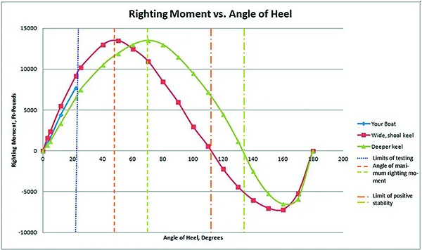
As we discussed in our 2015 report “Dissecting the Art of Staying Upright,” the GZ Curve (at right) can be used to calculate a stability ratio—the area circumscribed in the positive portion of the curve, divided by the area circumscribed by the negative portion of the curve. A higher ratio is better, and a common rule of thumb is that an ocean voyaging boat should have a ratio above 3.0.
The main article discusses creating a partial table based on heeling angles. Heeling a boat beyond 20 degrees is tricky, but if you can find boats with comparable design features and known GZ-Curves, you can visualize your own righting moment at various angles of heel, or at least roughly check the angle of maximum righting moment and the limit of positive stability. In the example case, “your boat” would likely meet or exceed the minimum LPS we recommend for offshore sailing (120 degrees), but without more information one can’t know for certain.
Once you have collected the data from your boat and other boats, you can create your own table using Microsoft Excel. Here’s how we do it.

- Create a table like the adjacent table with angle and moment in columns. Although we have entered units of measure (ft.-lbs.) do not include them in your table at this time. Place any columns used for intermediate calculations (unit conversions and heel angle) to the right and do not highlight these in the graphing process.
- Highlight and select the cells containing angle of heel, righting moment., and the associated headers.
- Click “insert” on the top tool bar, and then click “scatter” from the graphing options. This will accommodate angles at irregular intervals.
- Click “Design” and a dialogue box will let you chose the title style you want. You will also be able to enter the units and descriptions for each axis.
- You can save the graph as a PDF by selecting the graph and choosing PDF on the “save as” file type menu.
- Privacy Policy
- Do Not Sell My Personal Information
- Online Account Activation
- Privacy Manager
Ship Stability: Intact Stability Criteria and Inclining Experiment
Remember, in the first article of this series , we had mentioned that the value of GM needs to be obtained at various stages from design to construction of a ship. We had also mentioned that the purpose to obtain the value of this parameter at different stages differs from stage to stage.
The first time when the metacentric height of a ship is estimated, is during its initial design stages using the following methods:
- Empirical Formulae: A number of empirical formulae have been developed based on results of experiments made on different types of ship hull forms that help naval architects to approach to an expected value of metacentric height based on very basic dimensional parameters, like Length, breadth and Depth of the ship. Though the results obtained from these empirical formulae are not always accurate, they are used to arrive at an approximate value, which is very necessary, since ship design is a closed loop iterative process.
- Initial Hydrostatic Calculations: Once the hull has been designed based on the results obtained from the empirical formulae, it is necessary to calculate the metacentric height using the values of other hydrostatics. The formula used in this stage is as shown below:

The purpose to calculate the GM at this stage of design is to compare it with the value obtained from empirical formulae, and decide on the requirement of iterations in the hull design. For conventional designs, the percentage difference between the two would be within 2 to 3 percent. However, in case of novel designs, the values obtained at this stage is solely reliable, not the ones obtained from empirical calculations.
This article will discuss about the other two stages of ship design and construction where evaluation of GM is an absolute necessity and plays a major role in ensuring that the ship is stable, and built as per the requirements of the client.
Stability Criteria:
A number of criteria that are based on the shape and nature of the stability curve of a ship , are used to evaluate the stability of a ship. Remember, that since we are discussing about intact stability , we will only focus on intact stability criteria, i.e. to evaluate the point where the ship becomes unstable, the values of certain parameters will be obtained from the stability curve pertaining to the least favorable loading condition.
Some of the features of the stability curve that are studied here are:
- The steady heel angle in case of any heeling moment (wind moments, grain shift moments, etc.) This angle is shown in the following figure, at the point of intersection of the heeling curve and static stability curve. This angle plays a major role not only in determining the safety of crew, personnel, and cargo on board, but also helps in determining the angle at which the deck edge of the ship is likely to submerge. In other words, it helps us evaluate a ship’s resistance to capsizing, for a given loading condition.

- The range of positive stability for each loading condition. It is important to know this parameter because it gives us the angle upto which the ship can heel before capsizing.
- The magnitude of the heeling arm relative to the righting arm for every loading condition. The available difference between the righting and heeling arm gives us the allowable margin for further upsetting forces (wind, waves, etc.) before the ship attains negative stability.
Some of the criteria used to assess stability of a ship are also based on the dynamic stability of the ship. So, what is dynamic stability? Whatever we have discussed in the previous articles on stability, we have only dealt with Static Stability, i.e. stability of a ship when it is static. You could imagine it as if you have photographed a ship that is heeling, and studied its stability for that static condition in the photograph. However, dynamic stability deals with the study of stability over a range of angle of heels on the curve of intact stability.
For any given angle of heel, dynamic stability is the measure of the work done in heeling the ship to that angle, very slowly and while maintaining constant displacement. This is measured by the area under the static stability curve upto that angle, as shown in the figure below, where the grey shaded area is the dynamic stability of the ship at 30 degrees of heel.

So if at every angle of heel, the area under the static stability curve upto that angle is plotted, the curve for dynamic stability is obtained, which is shown in blue. This curve plots the amount of energy that the ship can absorb in order for it to heel upto a certain angle.
As per as dynamic stability criterion is concerned, we are more interested in evaluating the Residual Dynamic Stability of the ship in the following conditions:
- Shift of cargo within the ship.
- Presence of wind heeling moments.
- Wave heeling actions.
- Lifting of weight over one side.
All the four above cases result in a heeling moment which can be plotted similar to that in Figure 1. The area between the heeling moment curve and the righting moment curve (curve of static stability) is the Residual Dynamic Stability, and is less than the Dynamic Stability in absence of any of these upsetting forces. This value is evaluated for every loading condition and is tallied with a criteria set by governing bodies.
There are various international and national governing bodies that have established a set of criteria for ensuring adequacy in stability of ships. Some of these bodies are:
- International Maritime Organization (IMO)
- US Coast Guard (USCG)
- American Bureau of Shipping (ABS)
- Directorate of Naval Design (DND), Indian Navy
DND, India has set a series of stability criteria that are to be complied with, by all the ships serving for Indian Navy and Indian Coast Guard. Information regarding the same is classified, and hence, out of the scope of this article.
Our focus will be on the criteria set for merchant ships that ply on national and international waters . These criteria are laid down by International Maritime Organization (IMO) in The IMO Code of Intact Stability for Merchant Ships . This code specifies the formulae that are used to calculate:
- Heeling arm due to winds and rolling.
- Heeling arm due to grain shift or shift of dry cargo.
- Heeling arm due to crowding of passengers on one side.
- Heeling due to high speed turn.
The above four parameters are used to plot the heeling arm curves for each condition. The GM values are calculated by carrying out stability calculations at each loading condition considering reduction in metacentric height due to free surface effect. The results are all plotted on a stability curve. The values obtained from the curve should follow the following stability criteria for all merchant ships:
- The area under the GZ curve must not be less than:
- 055 meter radian up to 30 degrees.
- 09 meter radian up to 40 degrees or the smallest angle of heel at which flooding takes place through openings (this angle is called the Downflooding Angle ).
- 03 meter radian between 30 to 40 degrees or the downflooding angle (whichever is the least).
- Righting arm (GZ) must be greater than 0.20 meter at 30 degrees.
- Maximum righting arm should occur at an angle more than 30 degrees.
- Minimum metacentric height should be 0.15 meter.
The criteria mentioned above, are however, only a part of all the criteria mentioned in the code. If any criteria is not complied with, required changes are to be made in the loading conditions or tank capacities, or tank positions, depending on the criteria and which stage of design it is.
The Inclining Experiment:
An inclining experiment is carried out when the construction of the ship is completed up to a stage when all the components that contribute to the lightship weight have been installed. The primary purposes for carrying out an inclining experiment are:
- To measure the lightship weight of the ship.
- To find the vertical, longitudinal, and transverse positions of center of gravity.
- To calculate the metacentric height of the lightship.
It is always conducted by the shipbuilder because, at this stage, the shipbuilder must prove to the client that the lightship weight has not exceeded the design value. This is a very important milestone for the shipbuilder because, often, marginal increase in weight is likely to be observed due to various manufacturing constraints. It is due to this reason, a weight margin of approximately 15 to 20 percent is allowed in the technical contact. However, if the difference between the design lightship weight and that calculated during the inclining experiment exceeds weight margin mentioned in the contract, the shipbuilder must pay a penalty for each extra ton.
The experiment is carried out by inclining the ship using known weights. The known weight is first shifted to one side of the ship, and the inclination is measured by means of under deck pendulums placed at various longitudinal positions along the center line of the ship. The bobs of the pendulums oscillate on battens with readings marked on them. The length of the pendulums are usually about 10 to 12 meters, and they are submerged in oil or a dense fluid so as to increase damping.
When the ship is ready for the experiment, the weight is shifted on the deck in a transverse direction. This causes the ship to list. The ship is first allowed to settle down in this position and the deflection on the battens are measured on all the pendulums. The mean deflection is then calculated and considered as the value to be used for calculations. The same process is repeated by shifting the weight to the opposite side. In some cases, multiple observations are taken using different weights.

The above figure shows an inclining experiment in which a known weight of ‘w’ tonnes has been shifted by a distance ‘d’. The deflection of the pendulum is read as ‘BC’ on the horizontal batten. As a result of shift of weight on the ship, the center of gravity of the lightship shifts from ‘G’ to ‘G 1 ’ .
The metacentric height can then be calculated using the following expressions:

Where, ‘W’ is the measured mass displacement of the ship; AB is the length of the pendulum used; BC is the mean deflection read on the batten.
There are a number of precautions required to be taken in order to attain fairly accurate results, and they are to be ensured by the shipbuilder before the experiment commences:
- The experiment should be carried out when no beam winds are present. In case beam winds are unavoidable, corrections of metacentric height for beam winds are to be incorporated into the calculations.
- The ship must be floating upright at zero heel angle, and must not be restrained by mooring ropes.
- All lose weight present inside the ship should be restrained. Often, a lot of temporary structures like scaffoldings, wooden platforms, welding machines, etc. are present inside the ship during the experiment. They are either to be removed, or to be fixed to the ship so that they do not shift during the experiment. In the second case, their weights are to be recorded and the weight of the ship ‘W’ is to be corrected accordingly for calculations.
- Tanks should either be emptied or pressed to full capacity. In case none of that is possible, the level of liquid in the tank should be such that free surface effect is minimum, and corresponding free surface corrections should be made in calculation of the metacentric height.
- There are a number of personnel who are required to be on-board during the experiment. The number of personnel is to be kept to a minimum, and they are supposed to take pre-decided positions on the ship (which is usually along the centerline) before the readings are taken.
- All interconnections between tanks should be closed, irrespective of whether the tanks are empty, fully pressed, or partially filled.
- The draft marks of the ship must be read before the experiment begins, so as to ensure design trim and absence of a condition of loll.
- The density, salinity and temperature of the water on which the ship is floating, must be measured and recorded before the experiment. This density must be used to calculate the mass displacement of the ship ‘W’ . It is always recommended that the experiment is carried out in sea water.
Though the stability characteristics of a ship can be determined with considerable precision, most authorities and shipbuilders find themselves in a trap while quoting the primary characteristics like metacentric height and righting lever with great accuracy. This is because, a design cannot be replicated to the fullest, in the real world. Hence, a naval architect must be aware of the following reasons that often cause the real-time values to vary from the design values:
- Ships are not built exactly according to the lines plan, because the curvature of plates is almost always not achievable as per the lines plan. There is always a difference of 0.1 to 0.3 percent in the curvature, which when scaled up to the size of the ship, creates a shift from design values.
- The weights and center of gravity vary within a margin, due to the contribution of plate thicknesses and added weight due to welded joints.
- The accuracy of the actual KG of the ship as assessed, depends largely on the level of accuracy involved in the inclining experiment. It is based on the results of this experiment that the stability booklet of the ship is updated, and further stability parameters are calculated.
- One of the most important assumptions in all the stability calculations are that the ship is floating in an even keel or zero trim condition. However when values are recorded in real life, they are done in design trim conditions, and not at even keel. This results in a visible difference between design and practical values. However, recent design software are capable of carrying out all stability analyses in required trim conditions, which shoots up the level of accuracy.
All that we have discussed till now is, the stability of a surface ship when it is intact. How is the stability of a ship affected when its hull is damaged? How is a ship designed to be safe even if one or two compartments are completely flooded? These are aspects that fall in the category of Damaged Stability of Surface Ships, which we will be our topic in the next article of this series.
Disclaimer: The authors’ views expressed in this article do not necessarily reflect the views of Marine Insight. Data and charts, if used, in the article have been sourced from available information and have not been authenticated by any statutory authority. The author and Marine Insight do not claim it to be accurate nor accept any responsibility for the same. The views constitute only the opinions and do not constitute any guidelines or recommendation on any course of action to be followed by the reader.
The article or images cannot be reproduced, copied, shared or used in any form without the permission of the author and Marine Insight.
Do you have info to share with us ? Suggest a correction

Latest Naval Arch Articles You Would Like :

Effects Of Ice Accretion On Ship Stability
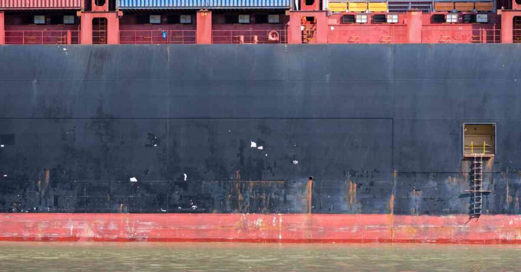
What are Freeing Ports On Ships?

What is Freeboard on Ships?

Superstructure Of Ships – Requirements For Design & Types Of Loads Acting
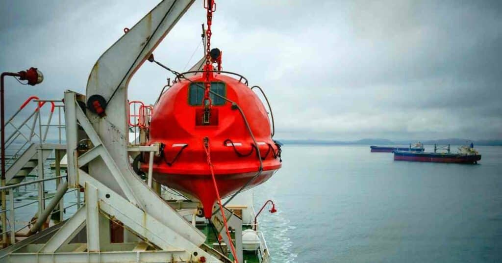
What are Tricing Pendants And Bowsing Tackles?

Types of Hulls Used For Vessels
Subscribe to our newsletters.
By subscribing, you agree to our Privacy Policy and may receive occasional deal communications; you can unsubscribe anytime.
How to calculate known weight ?
When G1G2 & LBP is not given, and we’re asked to find the GM of a vessel, do we use:
GM = (w × d × Original Length) ÷ (Displacement × Deflection); to find the answer?
Like say for example, a vessel with the displacement of 4950 t, which is initially upright when a weight of 25 t is moved across the deck 9.14m and at the same time a plumb line of 4.26m in length is deflected 0.3m. Find the GM.
GM = (w × d × Original Length) ÷ (Displacement × Deflection)
= (25t × 9.14m × 4.26m) ÷ (4950t × 0.3m)
= (973.41) ÷ (1485)
Therefore, GM = 0.655 m.
We didn’t really cover this topic well in class so I don’t know if I did the correct thing to find the answer (GM).
tan theta is BC/AB NOT AB/BC…
corrected Deepak. Thank you for keeping a sharp eye.
Leave a Reply
Your email address will not be published. Required fields are marked *
Subscribe to Marine Insight Daily Newsletter
" * " indicates required fields
Marine Engineering
Marine Engine Air Compressor Marine Boiler Oily Water Separator Marine Electrical Ship Generator Ship Stabilizer
Nautical Science
Mooring Bridge Watchkeeping Ship Manoeuvring Nautical Charts Anchoring Nautical Equipment Shipboard Guidelines
Explore
Free Maritime eBooks Premium Maritime eBooks Marine Safety Financial Planning Marine Careers Maritime Law Ship Dry Dock
Shipping News Maritime Reports Videos Maritime Piracy Offshore Safety Of Life At Sea (SOLAS) MARPOL
The GZ curve
Under theoretical conditions, a vessel's ability to stay 'on her feet' arises from two basic forces: the form stability which she possesses by virtue of her beam, and the pendulum effect of her ballast. The results of form stability are noticeable at relatively small angles of heel, while the righting effect of a ballast keel is at its greatest when the boat is on her beam ends. For a yacht to be properly seaworthy, her stability must stem from a healthy combination of the two.
When a yacht heels, her centre of buoyancy shifts to leeward as more of her volume is immersed on the downwind side (Fig A.l). Her centre of gravity (G), however, stays more or less where it was. This means that as her ballast is pressing down, the buoyancy is pushing up. Both are trying to return the boat to an even keel, and an equilibrium is reached with the sails, which are attempting to do the opposite.
The length of the 'lever arm' between the centre of gravity (G) and the moving centre of buoyancy (Z) varies with the angle of heel. It is known, logically enough, as GZ. A graph of the length of GZ (which, for a 35-footer with good stability characteristics may rise to between 2 ft and 3 ft) against heel angle gives a useful indication of a boat's range of stability in flat water. It demonstrates, amongst other things, the angle at which the value of GZ becomes negative, and at which the yacht's stability vanishes.
Fig A.2 shows clearly that the moderate-shaped Contessa 32 remains positively stable until she is virtually inverted at almost 160°. The flat-floored 'fin-and-spade
Appendix - Stability in Sailing Yachts 247
Was this article helpful?
Related Posts
- Course to steer at the turn of the tide
- Boat Handling under Power
- The trailing log - Seamanship
- Course steered and estimated position
- Preplotting and use of ships heading
- Efficient Sailing - Seamanship
Log in or Sign up
You are using an out of date browser. It may not display this or other websites correctly. You should upgrade or use an alternative browser .
How valid is Marchaj area under the stability curve for catamarans?
Discussion in ' Stability ' started by UpOnStands , Oct 10, 2017 .
Ad Hoc Naval Architect
UpOnStands said: ↑ Which question? Click to expand...
UpOnStands Senior Member
ummm, maybe, maybe not This is a cross sectional view of Shuttleworth Spectrum 42. Green area is roughly calculated to be 34 sq cm. Orange area is 68 sq cm with 13 degree heel. Sorry, but how does the Marchaj graph account for these changes in hydrostatic balance? Believe that is why Richard Woods referred to a theoretical crane lifting the windward hull. Just added the 3rd image showing the original displacement with 13 degree heel. Very little, if any, change in the hydrostatic balance.
Attached Files:
Screen shot 2017-10-12 at 8.34.30 am.jpg, screen shot 2017-10-12 at 8.36.35 am.jpg, screen shot 2017-10-12 at 8.45.32 am.jpg.
UpOnStands said: ↑ Sorry, but how does the Marchaj graph account for these changes in hydrostatic balance?.. Click to expand...
Back in the office again -- thanks for the explanation. Ad Hoc said: ↑ Then knowing the wind force is applied at a particular location on the sail, Click to expand...
UpOnStands said: ↑ No allowance is made for wind loading on the superstructure or indeed the hull itself? Click to expand...
interesting to know how accurately all the interaction forces can be calculated, but that is for another day rough analysis indicates that the Spectrum 42 lifts a hull at just 7-8 degrees of heel so the recommendation is to reef early? Thanks for the assistance.
So, new day. The RM curve for a catamaran is basically a really steep curve to some max value reached at, for lightweight vessel, 8-12 degrees. The rest of the curve is of little import since wind loads sufficient to reach RMmax will of course tip it over right quick. This is quite different from a monohull which interacts significantly over a very wide range of heel angles. Has anyone seen detailed wind load plots for a conventional catamaran? The wind load curve provided by Ad Hoc is, I assume for a monohull.
UpOnStands said: ↑ The wind load curve provided by Ad Hoc is, I assume for a monohull. Click to expand...
Ad Hoc said: ↑ No no no...ALL the curve is very important - that goes into dynamic stability and energy. Click to expand...
UpOnStands said: ↑ A captain with his catamaran heeled at 50 degrees is not going to be impressed with the vanishing small levels of energy available for righting the vessel. Take 20 degrees of heel, so flying a hull. Is the remaining righting moment energy of any import? Theoretically yes but in practice? Since the hull is already flying the wind is more than strong enough to continue to heel the vessel until capsize. Click to expand...
Sorry, I choose 20 degrees as it is significantly beyond the RMmax. Just to keep it clear, I am assuming the vessel has has ready passed through RMmax (which for most cats would <15%) and has now reached 20 degrees - not steady state at all.
UpOnStands said: ↑ Sorry, I choose 20 degrees as it is significantly beyond the RMmax. Just to keep it clear, I am assuming the vessel has has ready passed through RMmax (which for most cats would <15%) and has now reached 20 degrees - not steady state at all. Click to expand...
I am trying to link theory with the real world. Since this cat has lifted its hull the wind force exceeds that needed to reach RMmax . The wind continues to lift the hull as the RM decreases after RMmax. The wind is constant, the hull is rotating. Describe the theory.
UpOnStands said: ↑ Since this cat has lifted its hull the wind force exceeds that needed to reach RMmax . Click to expand...
- Advertisement:
Bon, simple answer to a simple question. Back to the "Wave Rider" capsize in Tasmania. Was the design the problem? Hull design or sail design? Apart from unstayed masts and furling systems, can we create a sail design that is self load spilling?
Is this mathematical model valid for any inclination angle of any floating body
- No, create an account now.
- Yes, my password is:
- Forgot your password?

Academia.edu no longer supports Internet Explorer.
To browse Academia.edu and the wider internet faster and more securely, please take a few seconds to upgrade your browser .
Enter the email address you signed up with and we'll email you a reset link.
- We're Hiring!
- Help Center

STABILITY AND TOTAL RESISTANCE ANALYSIS OF CATAMARAN FISHING BOAT FOR JAVA NORTH SEA AREA WITH HULLFORM MODEL AND FISHING GEAR VARIATION

2019, IAEME PUBLICATION
Substitution of cantrang fishing gear with other gears might give bad impact to the stability of the ship. But, catamaran boat type can improve the intended stability characteristics. The study was conducted using six variations of the catamaran hullform, namely symmetrical hull, asymmetrical straight inside hull, asymmetrical straight outside hull, which is each model has round bilge and hard chine variation. The study aims to find the lowest total resistance value. The hullform with lowest total resistance will be re-varied to 3(three) dif erent types of fishing gear, namely cantrang, purse seine, and bottom longline for stability analysis. The result shows that the round bilge symmetrical hull type has smallest resistance with value of Rt is 8.81 kN at 8 knots. Based on IMO MSC.36(63), the result of stability analysis shows all variations of fishing gear meet the established standard.
Related Papers
IAEME PUBLICATION
IAEME Publication
In this study, will be analyzed regarding the stability of the Batang type traditional fishing boat under 25 m is widely available in Indonesia already meet safety requirements seagoing or not, given the fishing boat of this type was developed traditionally by fishermen, where the resulting design is not planning through design phase, so often a ship that has been made does not have a reliable technical specifications. To solve this problem, the survey to retrieve data from 5(five) different types of traditional fishing boat below 25 m at Kabupaten Batang are carried out, then do redrawing of the existing ship, and finally the technical analysis of the design of the traditional fishing vessel for stability criteria is done. The recommendations for the design of traditional fishing boat under 25 m are given in this study corresponding safety criteria seagoing so beneficial to the safety of fishermen doing fish catching in the sea.
shanty Manullang
Fishing vessels used to catch resources from the sea has to pass some of the regulations from International Maritime Organization for sea-worthiness of the vessel especially about stability, resistance to acquire the highest velocity, and the vessel’s motion. This research discusses the effect of the vessel’s dimension and the hull shape by using the stability standard from IMO.The result shows that the ratio of the B/T which meets the stability criteria is 2.50 with the ratio of KG/H of the vessel is 0.65, with the assumption that the KG and H of the vessel are more than 0.70. Whereas if the resistance ratio B/T is big, the resistance for the vessel will be relatively smaller. In terms of the vessel motion, a vessel with a V-type hull will better than a U-type hull in seakeeping.
IPTEK The Journal for Technology and Science
I Ketut Aria Pria Utama
Asian Journal of Fisheries and Aquatic Research
Achmad Rizal
This study aims to analyze the ratio of the main dimensions of the vessel to see the performance of vessels with multipurpose gear. The research was conducted in February-March 2018 at the Karangsong Fish Landing Base (Ind: PPI), Indramayu. The object of research is the vessel used for fishing operations with multipurpose gear. The research method uses survey methods through the measurement of the main dimensions of fishing vessels, interviews and literature studies. The data obtained were then analyzed by comparative descriptive to compare the value of the ratio of the main dimensions of the vessel between Length and Breadth (L/B), the ratio between Length and Depth (L/D) and the ratio between Breadth and Depth (B/D). The calculation results of the ratio of the main dimensions of the vessel are then compared with the standard ratio values in Indonesia. Fishing vessels with multipurpose gear in Indramayu have good vessel motion characteristics but have an impact on slow speed, stron...
International Journal of Technology
Jurnal Teknologi A
OMAR YAAKOB
Zenodo (CERN European Organization for Nuclear Research)
Heffry Dien
Teknika: Jurnal Sains dan Teknologi
Romadhoni romadhoni
International Journal of Naval Architecture and Ocean Engineering
heri supomo
Proceeding of Marine Safety and Maritime Installation (MSMI 2018)
Shanty Manullang
RELATED PAPERS
European review of aging and physical activity : official journal of the European Group for Research into Elderly and Physical Activity
Leanne Groban
Filipa Palha
IEEE Transactions on Magnetics
Daniel Prober
Investigacion En Enfermeria Imagen Y Desarrollo
ANA JANNETTE MONTANEZ NINO
Semina: Ciências Biológicas e da Saúde
Edson Varga Lopes
Bangladesh Medical Research Council Bulletin
Mozammal Hossain
Journal of Stroke and Cerebrovascular Diseases
Kathryn Rexrode
Hwahak Konghak
Woo-Sik Kim
International Journal of Current Microbiology and Applied Sciences
anita kerketta
Pediatric Nephrology
Antônio Carlos Vieira Cabral
Les Champs de Mars
Olivier Passot
Gabriel Zazeri
Mr. Rohan S. Sawant DYPIT�
Acta Sociológica
Carmina Jasso López
muhammad subandi
Cancer science
Shiro Kitano
Social Epistemology Review and Reply Collective
James Marcum
Revista Acadêmica: Ciência Animal
Claudia Martin
Jurnal Elektronika dan Otomasi Industri
Rizky Ramadhan
Optical Modelling and Design
Sergi Gallego i Rico
Seminar Nasional Official Statistics
Azka Ubaidillah
hgvfgd ghtgf
Sergio Ruggiero
Journal of biotechnology & biomaterials
Ana Civantos
RELATED TOPICS
- We're Hiring!
- Help Center
- Find new research papers in:
- Health Sciences
- Earth Sciences
- Cognitive Science
- Mathematics
- Computer Science
- Academia ©2024
IMAGES
VIDEO
COMMENTS
The stability curves of the catamaran models are presented in Figure 9 to illustrate the variation in maximum GZ and range of stability. The GZ values presented are for full scale yachts, assuming ...
The Gz curve illustrates the relationship between the three key factors that determine the boat's static stability:~. The Centre of Gravity, the Centre of Buoyancy and the varying length of the Lever Arm. the Centre of Gravity (G) through which gravity exerts a downward force equal to the displacement of the boat, and.
Since metacentric height is directly related to the righting lever (GZ) and angle of heel, the curve of static stability is a plot between the righting lever and angle of heel. Figure 1: Static Stability Curve / GZ Curve of a Surface Ship. The above graph is plotted assuming that the ship is in static condition.
Righting arm (GZ) stability curves for a typical catamaran and a typical narrow, deep-draft, heavily ballasted monohull. Note similarities to the ideal curves in the last figure. To translate this into real-world terms, we need only compare the curves for two real-life vessels at opposite extremes of the stability spectrum. The curve for a ...
Stability Curves: GZ at all angles of heel To prepare a stability curve, the designer must find GZ for each angle of heel. To do this, she must compute the location of B at each angle of heel, and determine the height of G above the base of the keel (the distance KG). ... There are tens of thousands of catamaran sailors out there who would seem ...
This can be used to find moment of statical stability at any given angle of heel. Righting Moment (t-m) = GZ x Displacement of the ship. > Initial metacentric height (GM) - Can be found by drawing a tangent to the curve through the origin and then erecting a perpendicular through the angle of heel of 57.3 degree.
8. Correct a GZ curve for a shift of the ship's transverse center of gravity and interpret the curve. Draw the appropriate sectional vector diagram and use this diagram to show the derivation of the cosine correction. 9. Determine the initial slope of the GZ curve using Metacentric Height. 10. Analyze and discuss damage to ships, including: a.
Figure 6: The effect on the GZ curve of a simplified catamaran (hulls of square . crossection 1 m by 1m, floating at half depth) as the hull separation is varied.-2.000-1.000. 0.000.
Figure 4 shows graph of statics stability of this catamaran fishing vessel. At the initial position with heel 0 degree, the GZ length is zero. At the moment where heel is about 40 degrees, the GZ length is in the maximum value of 0.35 m and the empty condition is provided such result. Figure 5 shows the graph of GZ curve for full load condition.
curve (GZ curve) between the angles of heel of 30° and 40° nr between 30° and ef, if this angle is less than 4n°, should not be less than 0.03 metre-radian1. (b) The righting lever GZ should be at least 0.20 m. at an angle of heel equal to or greater than 300 . (c) (d) The maxi~1m righting arm should occur at an angle
GZ Curve of Catamaran Hull Design -0.4-0.2 0 0.2 0.4 0.6 0.8 1 1.2 1.4 1.6 1.8 0 5 10 15 20 25 30 35 40 45 50 55 60 65 70 75 80 85 90 95 100) Heel Angle (deg) GZ Curves and Area Under the GZ Curve of Catamaran Boat Design Boat Only Boat with Half Passenger Boat with Full Passenger Area Under The GZ Curve Criteria Value
A catamaran may have a greater heel if the specified damage is applied to just one demihull, as with larger vessels, and so this author recommends considering that case even for smaller vessels and making an assessment of longitudinal the trim and GZ reserve. ... The GZ curve at service speed therefore needs to be constructed from a ...
The GZ curve at no passenger condition Figure 8 shows the graph of GZ curve for full load condition. The GZ maximum is occurred in the heel angle about 35 degrees. ... Because this catamaran ...
Heeling "Your Boat" 22-degrees produces a GZ curve that is short and of little value. Most published GZ Curves result from both physical testing and computer modeling. As we discussed in our 2015 report "Dissecting the Art of Staying Upright," the GZ Curve (at right) can be used to calculate a stability ratio—the area circumscribed in ...
The required properties of the "damaged" GZ curve, namely max.GZ≥ 0.1m and the area under the curve of ≥0.015metre radians. shall be achieved within the positive range of the curve taking into account any restrictions imposed by Note 1.
Stability Criteria: A number of criteria that are based on the shape and nature of the stability curve of a ship, are used to evaluate the stability of a ship. Remember, that since we are discussing about intact stability, we will only focus on intact stability criteria, i.e. to evaluate the point where the ship becomes unstable, the values of ...
The length of the 'lever arm' between the centre of gravity (G) and the moving centre of buoyancy (Z) varies with the angle of heel. It is known, logically enough, as GZ. A graph of the length of GZ (which, for a 35-footer with good stability characteristics may rise to between 2 ft and 3 ft) against heel angle gives a useful indication of a ...
The RM curve for a catamaran is basically a really steep curve to some max value reached at, for lightweight vessel, 8-12 degrees. ... Looking at the wind moment curve applied to the righting moment GZ curve above, where is says first intercept, this would be the steady angle of heel. Your 20 degrees if you like.
3.1.2.1 The area under the righting lever curve (GZ curve) should not be less than 0.055 metre-radians up to θ = 30° angle of heel and not less than 0.09 metre-radians up to θ = 40° or the angle of downflooding θ f footnote if this angle is less than 40°.
2.3.1 Transverse Stability of Trimarans in Longitudinal Waves. Quasi-static assessments of an intact trimaran with the side hull positioned in the trough of the wave reveal a potentially dangerous condition due to parametric roll. Typically, GZ fluctuates around 0 (unstable) up to 5-10 deg of heel then goes positive.
The stability characteristics of the RO-RO ship, viz. GZ, GM, vanishing angle of stability and area under GZ curve are determined by well known Krylove's method. Fig. 3 shows the GZ curve obtained based on Krylove's method. Table 2 shows the comparison between the IMO criteria and the RO-RO ship. The curve of statical stability obtained ...
Our computer programs encompass Hydrostatics, cross curves of stability, flooding, (Symmetrical and asymmetrical), suitable for monohull, catamaran, trimaran structures, and GZ curve printout. Stability Booklets We, inconjunction with our partners, carry out inclining experiments and produce stability booklets and reports to comply with any ...
GZ ≥10° Departure Fishing Fishing (0% cargo, ground ground 100% (50% (100% consumable) cargo) cargo) 30.187 31.196 34.994 all pass 25.50 26.40 30.00 all pass Result Figure 10 shows GZ Curves of catamaran using bottom longline Table 8 Stability Criteria of catamaran using bottom longline Loading Condition No. IMO MSC.36 (63) Departure Value ...