

14 Steps To Wiring Your Boat
What you need to know to install or re-wire the electrical system on your boat. a step-by-step practical guide. covers planning, diagrams, wiring, batteries, over current protection and more..
I want to thank Ed Sherman for reviewing this page for accuracy.
A question often asked on boating and boat building forums, and by visitors to my web site, is: “I need a simple wiring diagram for a small outboard boat to wire up the lights and few other things, but no one seems to have one. Is there one, and where can I find it? Are there a set of step-by-step instructions?”
There are wiring diagrams, websites and forums that tell you how to wire an electrical system for large boats and bigger sailboats. But when it comes to small boats there is a distinct lack of information and diagrams for how to install a simple, safe, and reliable electrical system.
The following is meant to apply only to small outboard boats under 16 feet with 50 or 60 horsepower or less. It can be applied to slightly larger boats that have a simple 12V DC system using one or two 12V batteries.
Note 1 : I will not deal with the wiring specifically for the outboard motor and controls. Here is a web site where you can obtain wiring diagrams for most outboard motors. Most new outboards come with a wiring harness and a manual that has wiring diagrams. See Master Tech Marine Outboard Wiring Diagrams .
Note 2: If you are re-wiring a boat with an electrical system installed: Don't rip out that old system yet ! Use the old system to help make a plan in steps 1 through 7. Trace out each wire and put that on your diagram. This will make it far easier to locate wires and equipment. Wait until you actually start installing wiring in step 12. Then replace each set of wires with new. This may take a little more time, but will result in far fewer mistakes and less troubleshooting.
Note 3: Throughout this I will give references to the US Code of Federal Regulations (CFR) requirements that apply to boat manufacturers, and to the American Boat and Yacht Council industry standards. Examples: 33 CFR 183.401, or ABYC E-11. The US Coast Guard Regulations (the CFR) and the ABYC standards are good guidelines to follow for a safe and reliable electrical system. They are used by marine electricians, professional boatbuilders, designers, marine surveyors, and marine repairers. If that’s how the pros do it, so should you.
Step 1. Make a Plan. Decide what you want to install, and where it will go. See Electrical Planning
Step 2. Draw a simple electrical schematic (diagram) that shows each piece of equipment, the fuses, switches, and how all of this will be connected. This is not a diagram of where the equipment is located on the boat. That will come in Step 8. It is simply a diagram of the electrical circuits. Here are two alternative examples. (Click on the diagram to expand.) The first diagram uses a positive buss bar. The second omits the positive buss bar. For clarity I did not use color codes except red (positive) and black (negative).
Do not be concerned if you don’t know electrical symbols. Just make a box or circle and write in what it is, or you can use a picture of the item. As long as you understand what goes where, and how they are connected, it’s Ok. Remember, any 12V DC device must have at least a positive and negative wire connected to it. Put a plus or minus next to the wire or use red for positive and black for negative. On metal boats do not use the hull as a return (negative) path. Connecting your electrical system to a metal hull can result in stray current corrosion.
See also BoatUS diagram:
There are several ways to draw wiring diagrams. The most important thing is that you understand what you are diagraming. It needs to be simple enough and clear enough for you to be able to refer to it in the future and still understand what each item is, what the wiring is and how each item of equipment is connected to the electrical system. That way, in the future if you want to add or subtract equipment you can do so by referring to your diagram and determining where and how the new item fits into the system.
Step 3. Batteries: Decide where you will put the battery. Later we will decide the capacity and type of battery but for now we only need to decide where to put it.
The battery is the source of power for starting, instrumentation, and lighting. There may be a second battery on some boats for running a trolling motor or other equipment.
Batteries should not be too close to anything that can cause an accidental short. There should be 12 inches of space all around them. Batteries must not be directly under or over fuel lines or under other electrical equipment such as a charger or inverter. If they are, there must be a floor or panel separating them. ABYC E-10.7.5 and 10.7.6 Storage Batteries
Batteries need to be in a space that is ventilated to the atmosphere. 33 CFR 183.420(e) This applies to all batteries, not just lead/acid batteries.
Batteries must not move, so they have to be fastened down. 33 CFR 183.420(a)
There should be a tray under a battery for spilled electrolyte, or it should be in a battery box, and fastened down so it won’t move under any conditions. (ABYC E-10.7.2) The Coast Guard does not require a tray or a battery box but ABYC does require some means to contain spills. If it is strapped down in a tray, spilled acid won’t damage the boat and the battery won’t move. The terminals need to be covered with a boot or some other device that protects them from accidental contact with metal tools. But, if the battery is in a box the terminals are protected against accidental contact with tools, spills are contained, and it won’t move.
The battery should be close to the engine. Since starting current is so high, and the wires to the starter are not fused, you want to keep the wires as short as is practical.
The battery should be a combo starting/deep cycle battery, usually sold as a marine battery. An auto battery would do for starting and lights. But, for running a radio, and other electronics while anchored or fishing, a battery with a little deep cycle capacity is needed so the battery doesn’t go flat and leave you stranded when you try to restart the engine.
How big a battery (capacity, not physical size) do you need? That depends on the amount of load on the battery. I will show how to determine that in Step 12.
There is one non-electrical consideration; weight. Lead acid batteries can weigh up to 50 lb. Think about how the weight of the battery will affect weight distribution on your boat, especially if it is on the same side as the helm and controls. You may have to move it to balance the boat side to side. If you have a very low transom, how will the weight of the battery affect the water line at the transom?
Step 4. Battery Switch: Some people think that a battery switch is not necessary on a small boat. I think a battery switch is necessary to turn everything off when you are not using the boat.
Where the battery is located determines where the battery switch goes. It should be close to the battery but easily accessible to be switched off in an emergency. ABYC E-11.6.2.
A good brand is Perko but there are others. Avoid any battery switch that is not UL Marine Listed. There are cheap ones on the market that are not UL listed and can get hot and melt.
A battery switch must be ignition protected. (33 CFR 183.410)
Ignition protection means that it will not ignite gas fumes if they are present. This is extremely important if you have a gasoline fuel tank in the same compartment as the battery.
Use only ignition protected electrical components. You don't want anything in there that will set fuel vapors off. Batteries are not considered a source of ignition because there are no moving parts, but if you make accidental contact with metal tools it can create an arc. So, the terminals must be protected, and battery switches and other electrical equipment in this compartment must be ignition protected.
Buy a switch that has a provision for two batteries because you may want to add a battery in the future. The switch will have three positions. OFF, 1, 2, and BOTH. The 1 position connects the one battery and allows charging of that battery when the engine is running (if your outboard is large enough to have an alternator). The 2 position connects and charges the second battery, if there is one, and the BOTH position puts the two batteries in parallel doubling the battery capacity and charging both at the same time. You won’t need the BOTH and 2 positions now, but this gives you the option to add a second battery.
Step 5. Fuses: Next, install a fuse block close to the battery switch. Fuses must be within seven inches of the source of power (33 CFR 183.455) but you can go up to forty inches if the wire is sheathed. Standard wire loom is fine as a sheath. Be aware, the fuse is there to protect the wire, not the equipment. If you overload wiring it gets hot, melts and starts a fire. We will determine the size of the fuse later. See Step 12. Buy a fuse block with two fuse holders. That way you have a spare if the fuse blows. This is generally a good idea. When installing fuse blocks get ones with more fuse holders than you think you need. You will need them eventually. One or two extra fuse holders is good.
Step 6. Equipment Location: Determine where each piece of equipment will be.
Think about where you want things to go. Depth finders need to be where they are easy to see, but not blocking your vision when operating the boat. Radios should be where they can be easily reached, and for VHF, reach the mike. The back of the console or surface you are mounting them on needs to be easily accessible for access to the wiring.
Step 7 . Locate the fuses, buss bars and switch panels.
Decide where to put fuse boxes, buss bars, switch panels, etc. Each of these must be close to the equipment they power, and easily accessible to be worked on. They cannot be hidden behind equipment or inaccessible panels. This may sound obvious, but I have seen some very bad installations. Also, they should be protected from spray or rain.
Most electrical and electronic equipment comes with pigtails. Pigtails are wires coming out of the equipment and may only be a few inches to several feet long. Sometimes they have a connector attached to the ends of the wire. When determining where stuff goes consider the length of the pigtails, because you don’t want a rat’s nest of wires hanging loose.
Switch boxes: A box or panel where switches can be mounted to control stuff. On a small outboard boat this is usually the dash or the console.
Fuse block: A panel with fuse sockets on it. It can be open or covered.
Buss bar: A block with studs for connecting wires.
Typical Buss Bar: This buss bar is for the negative wires. The large wire on the left is the battery negative.
There are some devices that are connected directly to the source of power and do not go through fuse blocks and switches. They need to always have power. One is the bilge pump. Bilge pumps may have a float switch that automatically turns the pump on when water in the bilge gets to a preset height. This won’t work if the pump is not wired directly to the battery. It is not good practice to wire it directly to the battery though. Wire it to the power input side of the battery switch. It is good to install a switch at the helm that turns the pump on manually.
If your boat has an anchor light, you may also want to wire the switch for the light directly to the power input side of the battery switch. That way you can turn on the anchor light when the battery switch is off.
Step 8. Make a diagram of the boat showing where the wiring, equipment and fuse blocks will be located.
Make a rough drawing of the boat looking down from the top. This is called a general arrangement and shows how the boat is laid out. Using your electrical schematic, put in where the equipment, fuse boxes, buss bars, switch boxes and wiring are going to go. Check this against the actual boat to make sure you aren’t missing something.
Wiring cannot go through pieces of equipment, pipes, tubes, and other solid objects. They can go through walls and bulkheads and panels. Wiring must be easily accessible for installation, trouble shooting and replacement. It must be fastened down at least every 18 inches (ABYC 11.15.4.1.9) so it isn’t or chafing on something. Where wiring goes through a bulkhead, wall or panel, it must have a grommet or padding to protect the wire. 33 CFR 183.445(a)
Your diagram may look something like this; (Click on image to expand)

Step 9. Wiring: Figure out how much wire you need, what size wire you need, and what color it should be. Wire standards.
What about the wires from the battery Switch to the starter? The wire needs to be a very heavy gauge, at least a 4 AWG on small outboard boats, because starters draw a lot of current. Both the positive and negative wires should be the same size. If the outboard has the wires for the starter already installed, the wires from the battery to the switch should be the same size as those wires. The engine manufacturer has determined the amount of amperage the starter draws and correctly sized the wires for the load.
The positive wire (red) goes from the battery to the input side of the battery switch. The negative (black) wire goes to a buss bar. One post on the buss is for the wire from battery to the engine block (ground). Another wire goes from the buss up forward to the dash. The others are for other equipment. There should be as many terminal posts as you need plus a few extra.
Color Codes: The positive wire should be red. Negative can be black, or yellow, or black with a yellow stripe. Throughout the boat negative wires should be black or yellow or a combination. AT the dash or console, all positive wires from the fuse block to the instruments and the equipment, should be color coded using the standard color codes for marine wiring. Direct Current Color Codes: From ABYC E-11.15.2.3 Table 11 and Table 12.
Direct Current Color Codes: From ABYC E-11.15.2.3 Table 11 and Table 12.
Color codes tell you what the wire is for. But label the wire on both ends. A simple piece of tape with a name written on it will do. They do not need to be fancy labels, but if you prefer, you can buy labels at electrical suppliers or hardware stores.
Wire must be marine wire. (33 CFR Sec. 183.435) Do not use auto wire. It is not made to the same standards as marine. Most marine wire is labeled UL 1426. It must be copper stranded wire. It does not have to be tinned, although tinned wire will last longer. On a small boat it is not necessary. Do not scrimp on wire though! Cheap wire could mean the difference between a reliable system and one that you constantly have trouble with. Buy good quality wire. I have seen 100 ft spools of Ancor 16 AWG Tinned Marine Wire for sale on-line for as little as $24.00 USD.
What size wire? American Wire Gauge (AWG) is in reverse order. The larger the number, the thinner the wire. The thickest wires are 00 or 0 AWG. The smallest gauge allowed on boats for a single wire is 16 AWG, or 18 AWG if it’s in a bundle or sheath (33CFR 183.425), but this may be way too thin for the equipment or the length of the wire run. The only exception to this is wire inside electronic devices or part of the electronic controls on the engine. 33 CFR 183.425(g)
The thicker a wire is, the less resistance it has. The longer a wire is the more resistance it has, and so there is a larger voltage drop. You want to minimize the resistance and the voltage drop. So you first need to figure out the wire size based on how many amps are being used, and then by how long the wire is. Use the tables in Appendix A, at the end of this page, to determine the correct size. Don't just guess at wire size and buy larger diameter wire such as 14 or 12 AWG. See Wire Size:
For the purpose of determining wire size, the fuse block the wire is coming from is considered the source of power. For the wires running from the battery to the starter, or to the under-dash fuse block, the battery is the source of power. In the two examples below the fuse block under the dash or console is the source of power.
Here is an example:
A Hummingbird Model 345C depth sounder draws 380ma (milliamps from the specifications). The installation includes a 6 foot power cable of 18 AWG wire. This may be fine for connecting it to a fuse block near the dash. But we need to size the cable running from the battery to the dash. It is going to be at least 10-12 feet long on a 16 foot boat. Double that length for the negative return wire.
Use table 3 in The Appendix for voltage drop. Most boat manufactures use wire rated for 105C (degrees Celsius - the temperature rating of the insulation on the wire). Looking at the table under the column for 105C we see amperages starting at 20 amps, 25 amps, 30 amps, and so on. Following the row for 20 amps to the left column we find 18 AWG.
From the table on voltage drop an 18 AWG wire 20-24 feet long (30 feet in the table) with a 15-ampere load will have less than a 10% voltage drop. But it can only be 18 if it’s in a sheath or bundle. So go up one size to 16 AWG.
Another Example:
Suppose I have three electronics running off a fuse block in the dash or console. Each piece of equipment requires 1 amp at 12 volts to run. The total amperage for the three items is 3 amps. From the fuse block in the dash or console to each item of equipment, there is a positive wire from the fuse to the equipment, and a negative wire running back to the buss. Using 1 ampere, we determine the size the wire should be, by using table 1 and 3 in Appendix A. For instance, if the positive wire is two feet long then the total length of positive and negative wires is 4 feet. Looking at the Table 1, the line for 18 AWG wire at 105C allows up to 20 amps.
So, we could use 18 AWG. Look at Table 3. We see that an 18 AWG wire, 10 feet long, will have less than a 10% voltage drop for up to 5 amperes. Again, we could use 18 AWG but since 18 AWG wire has to be in a bundle or a sheath we add a level of safety by using 16 AWG.
This is done using the tables developed by the US Coast Guard and ABYC. You don’t have to know any formulas to figure it out. The first table determines the wire size based on the load in amps and the second table the size depending on length and voltage drop. You use the larger wire if there is a difference.
See the table in Appendix A at the bottom of this page. or ELECTRICAL TABLE: 33 CFR 183.42: ALLOWABLE AMPERAGE OF CONDUCTORS FOR UNDER 50 VOLTS or: ELECTRICAL SYSTEMS VOLTAGE DROP
Step 10. Wiring tools. Wire connections (terminals). See Connectors :
Tools: Use good quality tools, especially good quality crimpers and wire strippers. Cheap crimpers make bad crimps. Bad crimps make bad connections. Poor wire strippers nick the metal conductor which may cause the wire to break or have a high resistance. See My Page on Practical:
Wire terminals must be used . Connections should never be a bare wire wrapped around a stud or post. This is bad practice, and can easily come loose or result in a high resistance connection. High resistance equals heat, which results in fire. Never use wire nuts to connect wires on a boat! They are prone to vibration and corrosion. ABYC E-11.15.3.7 Twist-on connectors (i.e., wire nuts) shall not be used.
Use crimp type ring or captive spade terminals. Captive spade terminals have a tang on the ends. This prevents them from being pulled off or slipping off the stud or post. Connections must resist being pulled off. In the ABYC wire standard there is a table listing how much of a pull they must withstand depending on the size of the wire. A 16 AWG wire must withstand a ten lb. pull. A 4 AWG wire must withstand a 70lb pull.
You can solder connections if you like but crimp them first . ABYC standards do not prohibit soldering, but they do not allow soldering to be the sole source of support for the connection. (ABYC E-11.5.3.8) This is because solder creates a hard spot in the wire which is not as flexible as the wire itself and not as resistant to flexing and vibration. So, if you solder you must also crimp. Crimp first, then solder.
Seal wire connections with a good waterproof sealant , usually marketed as dielectric grease. There is no requirement to do this, but it prevents water from getting in the connection and wicking up the inside of the wire insulation or corroding the connector.
My method. I do not solder. First I slide a short length of heat shrink tubing onto the wire. https://en.wikipedia.org/wiki/Heat-shrink_tubing How long it is depends on the wire and connector size. Usually if the tubing extends about 1/2 inch (1 centimeter) beyond the end of the connector, that is enough. Then I use dielectric grease. See Wikipedia on Dielectric grease . Dielectric grease is non-conductive grease, usually silicone that is also waterproof and can be used to seal connectors. Before crimping the wire in the connector, I squirt a little dielectric grease into the connector where the wire goes. I then insert the wire and crimp it. Then I slide the tubing down over the connector and shrink it with a heat gun or hair drier so it seals itself around the wire and connector. The combination of grease and heat shrink tubing should keep the water out.
Heat Shrink Tubing And Connectors, AAA protection, How to install and repair. http://youtu.be/jCRsx38WRw8
How to get a good crimp: Marine How to: Wire terminations: https://marinehowto.com/marine-wire-termination/
Step 11. Fuses . How big should your fuses be?
Fuses are rated by amperage and protect the wire from overheating and fire. Fuses must be rated at the same or less rating of the wire. If you have a wire that is rated at 15 amps you need a 15 amp fuse. Each circuit is rated for a certain amperage, such as 15 amps or 20 amps, and more equipment is not added to the circuit if it would cause it to draw more current than the fuse is rated for.
This can become an issue on little boats too if you have more equipment, or something like a powerful stereo system that draws a lot of amperage. Then it should have its own circuit and its own fuse for the circuit.
The question is how many fuses in the block? That depends on how much stuff you are running. I would have a fuse for the lights, one for the instrumentation, and one for any electronic devices, plus a spare. That is four. But for expansion maybe a six or 8 fuse block would be better. Again, in the future you won’t have to buy a new block. See Overcurrent Protection:
Step 12. Installing equipment .
Start with the battery, the battery switch, and the main fuse block.
Selecting a Battery: Batteries are rated by voltage and capacity. We are using a 12V battery. There are two ratings, CCA and MCA See Batteries at:
CCA Means Cold Cranking Amps. MCA means Marine Cranking Amps. These are measures of how many amps the battery can deliver for 30 seconds and maintain the voltage at 12V. Basically the higher the CCA rating the longer the battery will maintain its voltage. Batteries are also rated by amp-hours. 1 amp for 1 hour is 1 amp-hr. Generally the rating is based on how many amps the battery will discharge for 20 hours until the charge drops to 10.5 volts. The higher the amp hour rating, the longer the battery will power your equipment. Also, batteries are rated for Reserve Capacity which is how many minutes it will deliver the same voltage at 80 degrees. An average marine battery should have a Reserve Capacity of 60 to 90 minutes. Anything less is not adequate.
There are four types of batteries commonly used on boats, Wet Cell (also called lead acid, flooded, or flooded lead acid, and sometimes abbreviated FLA), AGM (Absorbed Glass Mat, Gel, and Lithium, but for now I’ll stick with the standard wet-cell battery. They are relatively inexpensive, can be purchased anywhere, and for a small boat, more than adequate. A battery with a CCA or MCA rating of 200-300 should do but we’ll determine that when we calculate the loads. See table below on how to calculate loads. Battery Capacity should be at least twice the load.
To calculate loads, list the equipment you are planning on installing. In the chart below the following items are listed. Navigation lights Bilge Pump Radio (Only when receiving) Depth Sounder engine electrical Instruments GPS Bait well pump Horn Radio TX. (VHF Marine radio. It draws more when transmitting)
Determine from the specifications for each item what the current load is in amps. Separate them into continuous loads (on all the time) and intermittent loads (only on when used). Determine how many hours they will be used. Multiply the amps times the hours to get amp hours. Add up the amp hours.
See Also Electrical Planning
Double the result to determine what the rating of the battery should be. For this case, 200.
Another consideration is the battery group size. Batteries come in different physical sizes. A Group 24 battery is 10 ¼ inches by 6 13/16 inches by 8 7/8 inches. A Group 27 battery is 12 1/6 inches by 6 13/16 by 8 7/8 inches. The physical size is determined mainly by how much space you have for the battery and its weight. A bigger battery weighs more. A large group size does not necessarily mean it will last longer. That is determined by the battery ratings for amp hours and reserve capacity. The most commonly used size on small boats is Group 27.
Install the battery box if you are using one, or a tray, then the battery. Now that you have installed a battery you can begin installing equipment. Install lights and electronic equipment. You want everything in place before you begin wiring. Put in switch panels and fuse blocks.
From Step 5. We need to determine the size of the main fuse at the battery. The continuous loads add up to 10.5 amps. The fuse in a DC circuit should be about 150% of the load so a 15 amp would be appropriate. (ABYC E-11.10.1.5.)
The fuses for each circuit of our example should be at least 3 amps except for the VHF radio because on transmit it draws 6 amps. So, use a 10 amp fuse for the radio circuit. Check the manufacturer's installation instructions for recommended fuse sizes for each piece of equipment. Remember, this fuse is to protect the wire to the equipment, not the equipment. Some equipment may have built in or in-line fuses for that purpose.
Step 13. Installing Wire:
Begin installing wire, starting at the battery and working outward to each fuse block and buss bar, and then on to each piece of equipment. Remember to follow the color codes and label the wires on both ends. If you decide to make any variations from your diagrams make sure you change the diagram for future reference.
Step 14. Turn on the power. Test by turning on each item, one at a time, to see if it works. Troubleshoot as you go. If there is a problem, fix it before you proceed. Once everything has been tested individually, turn on everything, one at a time, until everything is on. If a fuse blows or something doesn’t work the last item you turned on is where the problem lies. Turn everything off, fix it and then try again from the beginning.
An Excellent Article: Avoiding Boat Electrical Mistakes by Ed Sherman; Boat US Magazine https://www.boatus.com/expert-advice/expert-advice-archive/2016/august/avoiding-boat-electrical-mistakes
An excellent article by Owen Youngblood on Wiring Your Boat , from the Metal Boat Quarterly
How to Wire A Boat from New Wire Marine https://newwiremarine.com/how-to/wiring-a-boat/
The USCG Boat Builders Handbook for Electrical Systems is available on-line at https://safeafloat.com/wp-content/uploads/2021/04/I-Electrical-Systems-Final-4-14.pdf
Contact ABYC for a copy of E-11, AC and DC Electrical Systems on Boats. There is a fee. See: https://abycinc.org
Appendix A: Allowable Amperage and Voltage Drop Tables
Note: This is the table that is in the Federal Regulations. The Federal Regulation now uses the ABYC table. It is published in 33 CFR Subpart I sec 183.425. ABYC Standard E-11 has five separate tables based on how many conductors are in a wire bundle.
The table for voltage drop is below. This is only for 12V DC. Contact ABYC for a copy of E-11, AC and DC Electrical Systems on Boats. There is a fee. See: https://abycinc.org
This is the table to determine wire size due to voltage drop based on the length of the wire. This table is for 12 volts only. The top row is the length of the wire in feet. The first column below Total Amps, is the amount of maximum amperage. The number in the row to the right of the total Amps column, is the size of the wire for a 10% or less voltage drop. Example: 25 feet of wire (top row) at 15 amps (first column) the wire would be 14 AWG.
Navigation Lights: I added this section because many people asked for it.
Wiring Navigation Lights for boats with combination red/green bow lights and an anchor/sternlight on a pole. I have been asked many times if there is a standard wiring diagram for hooking up the lights on a small outboard or inboard boat. There are some variations on this but here is how I did it on my boat.
The below diagram is for small boats with a red/green combo light on the bow, and a single sternlight that can also be used as an anchor light. Usually these have a single switch with 3 positions; Off, 1. anchor light, 2. combo bow light, sternlight/anchor light, and instrument lights. The diagram shows a Cole-Hersee switch that is in common use, but there are other manufacturers that also make switches for this, such as BEM and Blue Seas. They all serve the same function. In this diagram the lights are wired directly to the battery. However, some people prefer to wire it through the battery switch so the battery is not discharged if the lights are accidentally left on. It is just a matter of switching the power wire from B on the lights switch, to the number one position on the battery switch.

© newboatbuilders.com 2007 All rights reserved. revised 03/17/2023
Created with Dreamweaver 21.2 ©newboatbuilders.com 2022 All Rights Reserved
Service Locator
- Angler Endorsement
- Boat Towing Coverage
- Mechanical Breakdown
- Insurance Requirements in Mexico
- Agreed Hull Value
- Actual Cash Value
- Liability Only
- Insurance Payment Options
- Claims Information
- Towing Service Agreement
- Membership Plans
- Boat Show Tickets
- BoatUS Boats For Sale
- Membership Payment Options
- Consumer Affairs
- Boat Documentation Requirements
- Installation Instructions
- Shipping & Handling Information
- Contact Boat Lettering
- End User Agreement
- Frequently Asked Questions
- Vessel Documentation
- BoatUS Foundation
- Government Affairs
- Powercruisers
- Buying & Selling Advice
- Maintenance
- Tow Vehicles
- Make & Create
- Makeovers & Refitting
- Accessories
- Electronics
- Skills, Tips, Tools
- Spring Preparation
- Winterization
- Boaters’ Rights
- Environment & Clean Water
- Boat Safety
- Navigational Hazards
- Personal Safety
- Batteries & Onboard Power
- Motors, Engines, Propulsion
- Best Day on the Water
- Books & Movies
- Communication & Etiquette
- Contests & Sweepstakes
- Colleges & Tech Schools
- Food, Drink, Entertainment
- New To Boating
- Travel & Destinations
- Watersports
- Anchors & Anchoring
- Boat Handling
- ← How-To DIY
Electrical Wiring on Boats
Advertisement

Here's The Essentials
There's nothing quite like a boat for testing an electrical circuit to its limits! At the best of times the cables and terminals must put up with a combination of the omnipresent salt atmosphere and vibration (the United States Coast Guard requires fuel tanks to be tested at up to 25 G's); at the worst of times these cables may be totally submerged in bilge water, or dripping with engine oil, or cooked at high temperatures. All too often, salt infiltrates terminals and wicks up conductors, causing corrosion and electrical resistance; vibration causes copper conductors to work harder and fracture; and oil and high temperatures degrade insulating properties, leading to short circuits. As electrical efficiency declines, equipment fails, and in worst cases fires are started.
It makes no sense to install high-quality, marine-rated electrical and electronic equipment on boats without at the same time using high quality, marine-rated cables and terminals to power the equipment. In the marine environment, "high-quality, marine-rated" is determined by the following:
- Tinned conductors, in which every strand of a cable is individually tinned to minimize corrosion.
- Multi-stranded conductors, which use what is known as Type 3 stranding to maximize flexibility and minimize the potential for work hardening and fracture.
- Heavy-duty, moisture- and oil-resistant, high-heat rated PVC insulation.
- Tin-plated, annealed copper terminals with a rugged nylon insulator designed to be double crimped so as to relieve vibration-induced stresses at the crimp.
- Heavy-wall, glue-lined, heat-shrink tubing to seal connectors against salt intrusion.
Ancor cables, terminals, and heat-shrink tubing are claimed to be built to meet these demanding standards. Properly installed, they will ensure the integrity of electrical circuits for many, many years to come.
Cable Sizing
Proper installation is primarily a matter of sizing a cable to match its tasks, using the correct tools to attach terminals, and providing adequate overcurrent protection with fuses and circuit breakers.
Cable sizing is simple enough. It is a function of the length of a cable (measuring from the power source to the appliance and back), and the current (amperage) that will flow through it. This can be found by checking the label on the appliance in the circuit, or the specifications sheet for the appliance. The longer the cable, or the higher the amperage, the bigger the cable must be to avoid unacceptable voltage losses. And there should always be plenty of extra margin for safety because an appliance may actually use more current than what it is rated for because of heat, low voltage, extra load and other factors.
For 12-volt circuits, the relationship between cable length, current flow, and cable size is given in the two tables below. Note that Table 1 presupposes a 3% voltage loss in the cable, while Table 2 presupposes a 10% voltage loss. What this means is that when the circuit is fully loaded (i.e. operating at rated amperage), the voltage at the appliance will be 3% or 10% below that at the battery. For example, if the battery is at 12.6 volts, the appliance will be seeing 12.2 volts (3% loss), or 11.34 volts (10% loss).
The cable sizing tables are used by running across the top row until the column with the relevant amperage is found, and then moving down the left-hand column until the row with the relevant distance is reached. The number in the body of the table at the intersection of this row and column is the wire size (in something known as the American Wire Gauge); the lower the number, the bigger the cable! Use this wire size (gauge) to find the correct product. But don’t hesitate to go to a heavier (fatter) wire than the table indicates.
Many appliances (notably lights) will run fine with a 10% voltage loss, but others are particularly sensitive to such losses (notably charging circuits, and some electric motors). In general, given the harsh realities of the marine environment, it's better to use the 3% volt drop table when sizing cables, rather than the 10% table. There's never a performance penalty if a cable is marginally oversized; there is always a performance penalty (and possibly a safety hazard) if it's undersized. ABYC and the United States Coast Guard require a not to exceed 3% drop for circuits involving the safety of the vessel or its passengers and in other cases.
The ground (negative) cable is as much a part of a circuit as the positive cable; it must be sized the same. In general, each appliance should be supplied from the distribution panel with its own positive and negative cables, although lighting circuits sometimes use common supply and ground cables to feed a number of lights (in which case the supply cables must be sized for the total load of all the lights).
* Current (amps) determined by adding the total amps on a circuit.
Terminals and Tools
Terminals need to be matched to their cables. A 16-gauge cable needs a 16-gauge terminal. However, the same-sized terminals are sometimes used for more than one cable size. Red terminals fit 22 to 18 gauge cables, blue terminals 16 to 14 gauge cables, and yellow terminals 12 to 10 gauge cables. In larger sizes, each cable has matching terminals.
The terminals are the weak link in an electrical circuit. If installed incorrectly, they're likely to create power-robbing resistance. Since resistance causes heat, fires can result from improperly installed terminals. Crimp-on terminals have gained universal acceptance in marine wiring, but to work effectively they must be put on with the proper tools. For marine electrical work you need a wire stripper (rather than a pocket knife, which is likely to nick the copper strands in the conductor), and a decent crimping tool. The crimper needs to be matched to the terminal size being crimped, and should preferably make a double crimp, once on the conductor and once to grip the insulation for strain and fatigue relief.
For the ultimate in terminal protection and longevity following crimping, a connection can be protected with a length of glue-lined, heat-shrink tubing. Properly applied, this will make the connection watertight; the connection should last the life of the boat.
Overcurrent Protection
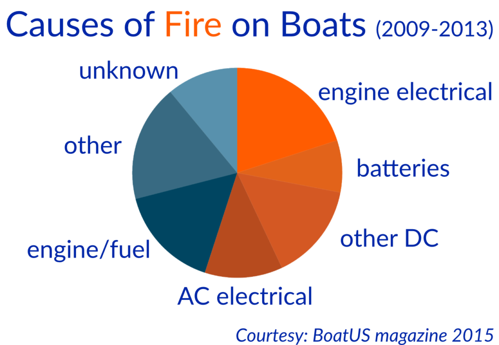
Overcurrent protection is a frequently misunderstood subject. Its need arises from the fact that if a short circuit develops in onboard wiring, high current flows occur, generating heat and causing cables to melt down. If the short is a serious one (a "dead short"), cables can burst into flames, setting fire to the boat and its surroundings. Electrical fires are among the most common fires onboard.
Fuses and circuit breakers, which collectively are known as overcurrent protection devices, are the primary defense against electrical fires. To be effective, they must meet two conditions: they must be properly sized for their circuit, and they must be placed as close as possible to the electrical source for the circuit.
Sizing is a function of the cable sizes in the circuit, not the amperage draw of the appliance in the circuit. A fuse or circuit breaker is sized to protect the smallest wire in its circuit. The current-carrying capability (ampacity) of this wire is determined by referring to Table 3, and then a fuse or circuit breaker is chosen with a rating no higher than this (it can be lower). If there is not an exact match between cable ampacity and available fuse or circuit breaker ratings, an overcurrent device with a rating of up to 150% of the ampacity of the cable can be used, but that's the limit.
There are two columns in the ampacity table-one for use outside engine spaces, and one for use inside engine spaces. The reason for this is that engine rooms are usually hot. Even before a circuit is turned on, a cable is warm. In these conditions it takes less current flow to bring the cable to a dangerous temperature than it does in a colder environment; hence, the de- rating in high ambient temperatures. If any part of a circuit runs through engine room spaces, the lower ampacity rating is used to determine the proper overcurrent protection for that circuit.
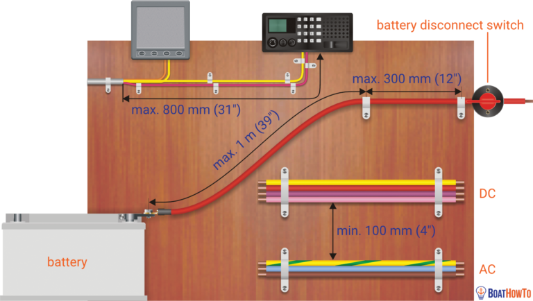
To be effective, overcurrent protection devices must be installed as close as possible to the source of power for a circuit. In fact, the ABYC recommends that circuits be fused within 7" of their connection to a power source. There are some exceptions to this recommendation, notably cranking circuits (these require no protection at all), circuits that are connected directly to a battery post (in which case the 7" is extended to 72"), and cables which are housed in a sheath (in which case the 7" is extended to 40"), but in general the point needs to be made: every circuit should be provided with a properly sized overcurrent protection device at the circuit's connection to a power source. If you've got a bunch of cables hot-wired to your batteries with no overcurrent protection, not only are these circuits not recommended, but you're also inviting a fire!
Circuit breakers and fuses are available for anything from a fraction of an amp up to 800 amps. There are also available a wide array of fuse blocks and distribution panels for mounting these fuses and circuit breakers. The complexity of wiring considerations can be seen in the following and above tables, all of which indicate that wiring should be done by an ABYC certified specialist unless you really know what you are doing and can follow ABYC standards.
Miscellaneous
Other important points to bear in mind when wiring boats:
- All circuits should be as high as possible with no connections in or near bilge water or damp areas.
- Use twisted-pair conductors for any wiring within three feet of a compass.
- You should never tap into existing circuits when installing new equipment; run a properly-sized new duplex cable (positive and negative conductors in a common sheath) from the distribution panel (or a source of power) to the appliance.
- All conductors should be labeled at both ends, and you should keep an updated wiring plan on board, to aid in future troubleshooting.
- Each circuit should have an independent ground cable, and all the ground cables should eventually be tied back to a common ground point which is grounded to the battery negative; if devastating stray current is to be avoided, this is the only point at which the grounds should be interconnected.
- Unless in a conduit, cables should be supported at least every 18".
- Although black is often used for DC negative, it is also used for the live wire in AC circuits. That means there is potential for dangerous confusion. Instead, you should use yellow for DC negative wherever possible.
- High-quality coax cable is critical to the effective functioning of radios; use only fully-tinned, 96% braid coax, and ensure that all connectors and terminals are properly installed.
- DC and AC wiring should be kept separate; if they have to be run in the same bundle, one or the other should be in a sheath to maintain separation and ensure safety.
- Be sure to isolate the batteries before working on the DC system, and, for safety's sake, shut off all potential AC power sources (the shorepower cord, an onboard AC generator, or an inverter).
Related Articles
The truth about ceramic coatings for boats.
Our editor investigates the marketing claims of consumer-grade ceramic coatings.
Fine-Tune Your Side Scan Fishfinder
Take your side-scanning fishfinder off auto mode, and you’ll be spotting your prey from afar in no time
DIY Boat Foam Decking
Closed-cell foam flooring helps make boating more comfortable. Here’s how to install it on your vessel
Click to explore related articles
BoatUS Editors
Contributor, BoatUS Magazine
Award-winning BoatUS Magazine is the official publication of Boat Owners Association of The United States. The magazine provides boating skills, DIY maintenance, safety, news and more from top experts.
BoatUS Magazine Is A Benefit Of BoatUS Membership
Membership Benefits Include:
Subscription to the print version of BoatUS Magazine
4% back on purchases from West Marine stores or online at WestMarine.com
Discounts on fuel, transient slips, repairs and more at over 1,200 businesses
Deals on cruises, charters, car rentals, hotel stays and more…
All for only $25/year!
We use cookies to enhance your visit to our website and to improve your experience. By continuing to use our website, you’re agreeing to our cookie policy.
843-297-8348 [email protected]
- E-Panel Builder
- Fully Custom
- Printed Contura II
- Etched Contura V
- Push Buttons
- Toggle Switches
- Circuit Protection
- Marine Lighting
- Accessories (all)
- Power Boxes
- SEAsafe Marine Storage
- Marine Wire
- Battery Switches
- Mounting Panels
- Plugs & Chargers
- Terminal Blocks & Bus Bars
- Terminals & Lugs
- Deutsch Compatible Connectors
- Meters & Gauges
- Merch & Gift Cards
- 1. Panel Buyer’s Guide
- 2. Switch Panel Options
- 3. Panel Material
- 4. Switch Label Options
- 5. Printed vs. Etched Switch Covers
- 7. Wiring Diagrams
- 8. Boat Wiring Basics
- 9. Before and After
- 10. LuxMatte
- Panel Projects
How to…
We get many questions over and over again, and in an effort to provide great content to our customers we’ve this how-to section with some guides below:
1. Wire A Boat
We’ve put together a this little newbie guide on How To Wire A Boat . It is by all means not-all inclusive, but should help some folks pickup some of the basics. View the complete guide here .
2. Wire A Bilge Pump
We recommend an ON-OFF switch for small boat bilge pumps with a a separate fused feed to the float switch direct from the battery. This makes sure your bilge pump is never accidentally shut of. It also gives a visual indicator at the switch when the float switch is working. View the complete guide here .
3. Create a Panel Template or Tracing
Often people want or need to mail their old switch panel in to have us duplicate a unique shape. Here’s our guide on how to mail in your switch panel with good results.
Practical Boat Owner
- Digital edition

Boat wiring explained for the practical sailor
- Pat Manley and Oliver Ballam
- February 13, 2024
Pat Manley and Oliver Ballam demystify boat electrics and explain wiring and the best techniques for its installation

Inserting a draw rod. Credit: Fernhurst Books Credit: Fernhurst Books
Electrical wire used on boats should be tinned (covered in solder) along its whole length.
This is expensive, so most production boats have ‘automotive-type’ wire, which allows corrosion to spread along the strands of wire under the insulation.

Automotive-type wire. Credit: Fernhurst Books
This makes it impossible to remake joints successfully. Where one end of a wire is located in a damp atmosphere, tinned wire should always be used.

Tinned marine wire. Credit: Fernhurst Books
Unless it’s unavoidable, don’t run wires through the bilge where their condition will deteriorate.
Running boat wiring
Use a push wiring threader to run wires through conduits and pipes.
- Insert one end into the conduit or gap through which you need to run the wire.
- Then push the threader through.
- Then use the threader to pull the electric wire all the way back through.
If you need to run wires straight through inaccessible spaces then draw rods are better because they are rigid and you can angle them to come out of, or go into, a space. They screw together and can be assembled ‘as you go’.

A set of draw rods. Credit: Fernhurst Books
Most alloy masts have internal conduits, provided to carry wiring running up the mast. Sometimes these are extruded as part of the mast and sometimes they are plastic conduits clipped or riveted onto the side of the mast.
Wires dropped through the main section of the mast will slap and chafe.

An alloy mast with conduits. Credit: Fernhurst Books
A push threader can be used to run mouse lines and cables up the mast’s conduit.
If possible, it’s usually easier to pull one existing cable back with a mouse line attached, and then attach the new cable and the old cable together to the mouse line.

Grommets to protect insulation. Credit: Fernhurst Books

Ducting to protect insulation. Credit: Fernhurst Books

Supported cable. Credit: Fernhurst Books
- Cable should not come under strain, which could cause connections to be pulled apart.

Corrugated trunking. Credit: Fernhurst Books

Beta duct trunking. Credit: Fernhurst Books
- Make a wiring diagram of any new work to be stored with the boat’s manual. If there are joints/junctions access points, try to indicate on the diagram where these points are.
Heavy-duty circuits
A DC electric motor will overheat and suffer early failure if the supply voltage is reduced.
Motors with high current requirements need special care with their wiring circuits to maintain an adequate voltage. Normally, a voltage drop of 10% is the maximum allowed.
The operating switch will not handle the required current, so a relay is introduced into the circuit.
A relay consists of an electromagnet that can be operated by the low current; its contactors then carry the high current required to operate the motor, or whatever.
This keeps the switching current low, but heavy-duty contacts handle the high current load of the motor.
Proper siting of the relay will keep the length of the high-current circuit to a minimum.
Let’s see why an electric windlass, for instance, might fail prematurely if its wiring has too much resistance: Say it has a maximum power of 1,000W and should be run at 12V:
- The current would be 83.33A at maximum pulling power: 1,000W ÷ 12V = 83.33A
- Say the resistance of the wire is such that there is a 10% voltage drop: 2V x 90% = 10.8V
- The current would now need to be 92.59A if required to pull its maximum load: 1,000W ÷ 10.8V = 92.59A because it would try to maintain power by drawing more current from the battery at the reduced voltage
- With a 20% voltage drop (to 9.6V), the current would be 104.2A: 1,000W ÷ 9.6V = 104.17A
- This would give a 25% current overload: 104.17A ÷ 83.33A = 1.25 leading to rapid failure
For the same reason, if you had the engine running, the voltage at the windlass would be about 13.5V.
With the engine stopped and the battery down from overnight use, the windlass voltage could easily be reduced to 10V or so.
Engine running: 1,000W ÷ 13.5V = 74A
Engine off: 1,000W ÷ 10 V = 100A
Which windlass motor is going to last longer?
You might think that the windlass motor is a fixed resistance so by Ohms Law, as the voltage decreases, so does the current. However, motors produce something called back EMF (voltage) which acts against the current flow.
This means that the operating current is optimal at rated speed. It’s at its highest when the motor is stationary.
Back EMF is too detailed to discuss here, but it’s why poorly supplied motors fail early.
Starter motors and sheet winches
These are operated with the engine stopped. Starter motors normally run for a very short time and have a relatively short run of very heavy cable.
Provided connections are clean and well made, they make only small demands on a dedicated engine start battery.

Relay to keep the switching current low
Sheet winches may have relatively long cable runs and the demands on the battery system can be significant, so that voltage drop at the motor needs to be minimised.
Adhere strictly to the manufacturer’s wiring requirements.
Bow thrusters and anchor windlasses
To keep voltage drop to a minimum, these are normally used with the engine running to prolong the life of their electric motors and to minimise battery drain.
Bow thrusters especially can’t be powered directly from the engine alternator , as it won’t produce enough current.
There are two schools of thought on powering these machines:
- An existing battery – engine or domestic Long, very heavy and expensive cables run from the aft battery bank. For a bow thruster these cables may carry 400A and may have a circuit length of 20m, in which case a cross-sectional area of 200mm2 may be needed for cables. That’s a diameter of 16mm! Windlass cables will be appreciably smaller as most windlasses draw more like 80-100A (typically 35-70mm²). If no bow thruster is installed this is the most common method for a windlass.
- A separate battery close to the demand The heavy cable length is kept to a minimum by placing a dedicated battery close to the windlass or bow thruster. This is charged by a smaller cable from the engine/charger. The charging cable needs to be rated to carry the maximum charging current and associated voltage drop only. The lower cost of the lighter cable, however, may be outweighed by the cost of the extra battery. The disadvantage of this method is the weight of this battery forward in the boat, although the total weight of cable and battery may be similar for both methods. It also complicates the charging system significantly, but this is the favoured option for bow thrusters.
Wire current rates
A wire must be capable of carrying the maximum current in the circuit. All wires have a current rating. A 5A wire must carry no more than 5A, and so on.
Note that wires bundled together can carry less current because they will heat up. Wiring for sensitive equipment should not allow more than a 3% voltage drop.
Normally this is more restrictive than the current rating because it depends on the length of the wires (both positive and negative).
Other wiring may be allowed a 10% voltage drop along its total length. Even 10% will usually require a larger diameter of cable than the current carrying capacity.
The cable should be specified to suit the largest requirement. 12V circuits will always require heavier cable than 24V circuits, because with 24V the current is halved for the same power appliance. This is why larger boats (with longer runs and heavier loads) will run a 24V system.
Wire sizes required for a given length of cable run
(Length is the sum of the positive and negative wires) – see tables below
When installing new equipment you’ll need to:
- Decide where you will need to power the equipment from: The battery (if it needs to be on all the time); The battery isolator (best if it is turned off by the battery isolator); An existing bus bar or circuit breaker.
- Check the wire size required, according to its length and the current it has to carry, from the table above.
- Run a new positive wire from the above source to a fuse holder or circuit breaker.
- Run a new positive wire from the new fuse holder to the new equipment.
- Run a new negative wire from the existing negative bus bar or a new one as appropriate.
- Once you’ve checked your work, fit an appropriately-sized fuse, as recommended by the equipment manufacturer.

Credit: Fernhurst Books

- The fuse or circuit breaker should be fitted as close as practicable to the positive source.
- If you have an ammeter, its shunt should be fitted in the negative battery cable.
- Equipment supplied direct from the battery MUST have the negative cable connected via the shunt and NOT taken direct to the battery’s negative terminal.
- If you are planning to add more than one device, you may need to add a positive and/or negative bus bar.
- When connection to the battery is necessary, some vessels will have a bus bar already – can you connect to this rather than adding more wires to the battery? Is the bus bar and supply wiring capable of carrying the extra current?

New protected wiring insulation. Credit: Fernhurst Books
Continues below…

Understanding boat electrics: switches and relays
Pat Manley and Oliver Ballam demystify boat electrics, starting with switches and relays

Understanding electrical wiring connections for boats
Pat Manley and Oliver Ballam demystify boat electrics and explain how to use and make secure electrical wiring connections

Understanding electrics: insulating & signal wire connectors
Oliver Ballam and Pat Manley demystify boat electrics and explain various types of electrical connectors and their uses on board

Soldering boat wire: joints and connections
Oliver Ballam and Pat Manley demystify boat electrics and explain the best techniques for soldering and de-soldering connections
The third edition of Essential Boat Electrics (Fernhurst Books, £16.99) is available at fernhurstbooks.com .
Written by Oliver Ballam and the late Pat Manley, it’s a practical guide – with simple language and clear diagrams – to allow owners to tackle electrical jobs on board.

There are tutorials, from wiring a circuit, understanding switches and relays to troubleshooting electrical faults, all using easy-to-follow photo sequences.
The book also looks at tasks such as choosing solar panels and batteries and connecting navigational instruments.
Buy Essential Boat Electrics from Amazon (UK)
Buy Essential Boat Electrics from Amazon (US)
Buy Essential Boat Electrics from Foyles (UK)
Buy Essential Boat Electrics from Waterstones (UK)
Buy Essential Boat Electrics from Google Play
Note: We may earn a commission when you buy through links on our site, at no extra cost to you. This doesn’t affect our editorial independence.
Enjoyed reading boat wiring explained for the practical sailor.
A subscription to Practical Boat Owner magazine costs around 40% less than the cover price .
Print and digital editions are available through Magazines Direct – where you can also find the latest deals .
PBO is packed with information to help you get the most from boat ownership – whether sail or power.
- Take your DIY skills to the next level with trusted advice on boat maintenance and repairs
- Impartial in-depth gear reviews
- Practical cruising tips for making the most of your time afloat
Follow us on Facebook , Instagram, TikTok and Twitter
- Consultation & Design
- Installation & Service
- Boating Tech Talk
- Case Studies
- Testimonials
- PYS Merchandise
- PYS Donation

How To Create A Wiring Diagram For Your Boat
Most new boats include a drawing that outlines the entire electrical system, however these become outdated very quickly as new equipment is installed. For older boats, they can be completely out-of-date or non-existent. Putting together a simple diagram of your boat's electrical system may seem overwhelming but it isn't as hard as you think. It just takes time, patience and the realization that it cannot be completed in a day and will be an on-going project.
Where to Start? If you have an existing drawing, we recommend you enlarge it and make clear notes regarding any changes. If you don't have a drawing, start with a large sheet of paper, and begin with the batteries and the main DC system such as battery chargers, inverter, busbars, and switches. Also include wire size and fuses.
Labelling - In order to complete the schematic drawing, you will have to figure out what each wire is for and where it goes. Once you have established the purpose of the wire, attach a label to identify it. Use marine specific labels or a high-quality labeller. Oils and moisture in the engine room can cause most home office labels to dissolve. While you are tracing each wire, look for signs of chafing or small bumps and change as required.
Many electrical problems start with the connectors, the wires are in a damp environment and are subject to constant vibration. A good connection starts with a good crimp and the secret to a great crimp tool is that it does not pierce the insulation on the wire. Our favourite is the FTZ Cycle Crimp tool that is specifically designed for heat shrink terminals and splices. The bare wire at each end of the connector sleeve must be sealed with heat shrink. Make sure you have a number of different sizes on board, both for correct wire gauge and ring size, along with a good heat shrink torch, such as the Ancor Mini Butane or Butane Pro.
Marine terminals feature pure electrolytic copper to offer the least electrical resistance for best current flow. They are tinned to prevent corrosion from salt and moisture. Ensure that they are UL listed and designed to be used on flexible stranded wire. Look for terminals with a seamless, flared barrel design that makes it easy to insert the wire and gives maximum strength when crimped. A closed-end seals out moisture so your cables stay dry and do not corrode over time. You may be tempted to use less expensive terminals designed for your car or truck but don't.
Along with your crimper, terminals and heat shrink, you should pick up a small tinned wire brush. To ensure you have the best connection possible, keep the posts and connectors free of corrosion. Your onboard fuse kit should include a complete set of both glass and blade (automotive style) fuses. As you are going through and identifying each wire run, make a list of fuses you use. Many marine stores carry small, inexpensive kits with a great assortment. A really great tip is to zap strap or tape an extra fuse in or near the location of the actual fuse. If you have an inverter/charger, make sure you have a Class T fuse onboard as they can be difficult to source while boating
ABYC Standards - If you are thinking of doing any wiring as a DIY project, get a copy of the appropriate American Boat and Yacht Council (ABYC) standards. Boat manufacturers use these standards as an absolute rulebook to design and build safer boats.
There are symbols used by designers and electricians for each device, but if you don’t know the symbols don’t worry. Draw a square, label it with the name of the device (inverter, switch) and show the wires that are connected to it. For DC wiring, positive wires are red, negative wires are yellow (or black in some cases).
Your boat wiring system should have a marine grade main battery disconnect switch which allows you to open the switch to turn everything off at once. There are some devices on your boat that you do not want to shut off when you turn off the battery switch such as the automatic bilge pump, an automatic fire-fighting system, or propane detector. These will be wired directly to the battery and must be protected with an inline fuse at the beginning of the circuit.
On most boats the ground reference is the engine block which is, in turn, connected to the water via the propeller shaft. Determine if you have a bonding buss for the underwater metals, this is a green wire (or a copper strap) that runs through the length of the boat and connects all of the underwater metals. Although grounding and bonding are frequently referred to interchangeably, a bonding system electrically connects the boat’s underwater metal fittings, such as through-hulls, seacocks, rudders and struts through zincs to protect it from corrosion.
While you are putting together your schematic, make a note of each of the components (ie inverter, charger, generator) with the model number. Then collect all of your Owner’s Manuals, we recommend storing them in an accordion file or binder. While all of this information is available on-line, boaters do not always have access to the internet. The back pages of these manuals typically contain a list of common error messages and resets along with proper installation wiring diagrams. Many boaters include the original bill of sale inside the front cover of the actual manual, which includes a description and date of purchase.
Most yacht clubs, cruising groups or Power Squadrons offer electrical courses either in the evening or on the weekend. For those of you who really want to get to the next step of understanding the what and the why of marine electrical, purchase and read Nigel Calder’s book called “Boatowner’s Mechanical and Electrical Manual”, it is the industry "go to" for marine electrical repair.
A good electrical diagram will save you money because there is nothing more beneficial to a technician or mechanic than an up-to-date schematic. It can save hours of trouble-shooting. As well, the process of spending time with your electrical will help you become more familiar with your boat and get you back on the water faster.
About the author: Jeff Cote is the owner of Pacific Yacht Systems, a full service shop delivering marine electrical and navigation solutions for recreational boats. Visit their website and blog for info and articles on marine electrical systems, projects and more: www.pysystems.ca.
Related Content

Boating Tech Talk Our Marina Only Has 15A Shore Power but I Still Keep Tripping the Breaker?

Boating Tech Talk 3 Bank Battery Charger for 2 Battery Banks?

Boating Tech Talk Can You Explain Battery Combiners, GFCI/ELCI vs. Galvanic Isolators?

Boating Tech Talk Adhesives for Flexible Solar Panels?

Boating Tech Talk Explain Wire Size and Fusing?

Boating Tech Talk AIS Receiver vs. Radar Reflector?

Boating Tech Talk Advice on Selecting an Inverter/Charger?

Boating Tech Talk Common Reasons for Battery Damage?

Boating Tech Talk Advice on Marine Cameras?

Boating Tech Talk How are my Tach and Alternator Related?

Boating Tech Talk Experience with Thermal Cameras?

Boating Tech Talk Automatic Combiner Relay or Voltage Sense Relay

Boating Tech Talk Can You Explain the Difference Between Poly and Mono Solar Panels?

Boating Tech Talk Two Batteries Are Hotter and Need More Refills Than the Other Batteries in the Bank - What Causes This?

Boating Tech Talk What Is The Charging Sweet Spot & Maximum Discharge For My Batteries?

Boating Tech Talk 12V or 24V Thruster?

Boating Tech Talk How Do I Prevent Galvanic Corrosion on My Boat From Boats Around Me?

Boating Tech Talk Gel Battery Rate of Charge?

Boating Tech Talk Advice on Improving Alternator Ouptut?
Boating tech talk help me understand my fuse block.
Copyright © 2024 Pacific Yacht Systems.
Contact Us 604.284.5171
PYS Partners | Privacy Policy | Terms of Use


Home » Blog » Boat maintenance & DIY » Learn boat wiring from the experts
Learn boat wiring from the experts
By Author Fiona McGlynn
Posted on Last updated: August 18, 2023
Our review of Boat Electrics 101 , a new online course, co-developed by marine electrics expert, Nigel Calder.
When we bought our 1970s-era sailboat, the boat wiring was a disaster.
We soon discovered a rainbow spaghetti mess of unlabeled electrical wires behind our DC electrical panel. Legacy marine electrical systems from a previous “rewiring” made trouble-shooting and tracing wiring runs exasperating. Lights and pumps regularly failed and we once lost power entirely (despite being on shore power).
In short, living on a poorly wired boat was a nightmare. We needed to learn about our boat’s electrical if we were ever going to go bluewater cruising.

A quick note that this post contains affiliate links (so if you purchase through a link we’ll earn a small commission). We received free access to this course in exchange for a fair and honest review. All the opinions are our own.
Learning how to wire a boat
The good news is that while boat electrical may seem intimidating, it’s actually not all that difficult to get the hang of—but it does have to be done right!
The challenging part was finding a good teacher. We hired an electrician we found on Craigslist to show us the ropes, but this proved to be a complete disaster (with him shorting out the dock mains at our marina and frying our inverter).
After that experience, we resolved to teach ourselves, sorting through the good, bad, (and sometimes, downright dangerous) boat electrical advice available online.
Fortunately, there is now a FAR better way to learn boat wiring…
Boat Electrics 101
Boat Electrics 101 is the online course I desperately wish we’d had at the time. It launched in 2021 and was created by arguably the world’s smartest people on marine electrics including boat systems guru, Nigel Calder.
If you’re not familiar with Nigel, you’ll find his mechanical and electric books in just bout every bluewater cruiser’s library. These guys really know what they’re talking about!

In the course you’ll learn:
- The basics of how electricity works
- Electrical system components and how to safely connect them
- How batteries work (and what you can do to double or triple their lifetime)
- Energy system design: how to balance your energy storage, consumption, and generation
- How to plan a (re)wiring of your boat (including making your own boat wiring diagram)
Unlike my grade 10 science teacher, the course does a great job of taking an important concept and breaking it down with animations, diagrams, and videos.
For example, In one module, Calder demonstrates the importance of circuit breakers by driving a screw through an unprotected wire. The cable immediately went up in flames, filling the room with smoke! Lesson learned.
Best of all, all of their materials follow ABYC and ISO standards. Both Nigel and Michael have been members of American Boat and Yacht Council (ABYC) and the International Organization for Standardization (ISO) committees, so they know the rules and best practices better than anyone.
I’ve taken Boat Electrics 101 and can’t say enough good things about it. If you sign up now, you can take advantage of their early bird offer ($199) and save $100 . Oh, and you keep your access to the course forever (even as they add new material). Even if it saves you hiring a marine electrician just once, the course more than pays for itself.
The rewards of doing it yourself
Learning how to wire a boat was not only rewarding but it made us more capable, self-sufficient boat owners. It’s an essential skill for people with older boats, but even new boat owners will find there comes a day when an electrical component fails or they want to add more bells and whistles.
We’ve saved a lot of money by doing our own marine electrical work (not to mention avoided days stuck in port waiting for a professional marine electrician). So, don’t let marine wiring intimidate you. With the right knowledge and tools, you’ll be well on your way to doing your own marine electrical.

Fiona McGlynn is an award-winning boating writer who created Waterborne as a place to learn about living aboard and traveling the world by sailboat. She has written for boating magazines including BoatUS, SAIL, Cruising World, and Good Old Boat. She’s also a contributing editor at Good Old Boat and BoatUS Magazine. In 2017, Fiona and her husband completed a 3-year, 13,000-mile voyage from Vancouver to Mexico to Australia on their 35-foot sailboat.
Sunday 23rd of January 2022
I learned the hard way about boat electrics when locked onto the engine block and a battery charger on a sailboat connected to shore power with a faulty ground. I was being tazered by 240v.
My friend saved my life by pushing me off the engine with a broom handle!
Yes, understanding boat electrics is something that is as important as navigation!
Oh my gosh, that sounds terrifying! What a nightmare. I'm glad you're okay. That was some good quick thinking on your friend's part!
Terms and Conditions - Privacy Policy

The $tingy Sailor
Diy trailerable sailboat restoration and improvement without throwing your budget overboard.

How to Completely Rewire Your Sailboat
It’s an enduring truth that appearances can be deceiving, especially with electrical systems. When I inspected Summer Dance before buying her, the electrical system looked like one of the boat’s strong suits. It had an upgraded panel and a new battery. The wiring was all original except for spliced connections to the panel. There weren’t any added accessories so the system was simple and I expected it to be relatively problem-free. Granted, I’m no marine surveyor and if I had ordered a survey, it would have caught many of the problems that I later discovered.

The first problem that I had was an intermittent stern light connection. Next was an intermittent primary ground wire. When I removed and disassembled the West Marine breaker panel to clean it, all the spade connectors had some level of salt water corrosion. Then the main ground conductor failed entirely and I had to replace it. Upon further inspection, all the conductors to the battery and breaker panel showed extensive corrosion for several feet under the insulation that made them brittle and prone to breaking. There was no overcurrent protection at the battery at all. Since electrical system failures are a major cause of onboard fires, it’s also true that what you cannot see can hurt you.

When I started adding accessories like the music system , LED strip lights , anchor light , and autopilot , it became clear that the four circuit panel was going to be inadequate.

Rather than connect the new accessories to an unsafe and crumbling foundation, I decided to rewire the boat so that everything was new and built (as close as practicable) to the American Boat and Yacht Council standard E-11 – AC & DC Electrical Systems on Boats .

I say “as close as practicable” to the ABYC standards because the ABYC is intended for boat manufacturers and service centers, not boat owners. Their standards documents are not generally available to the public. You have to pay an expensive membership fee and then purchase the standards for $195 . Those costs would exceed this project’s entire cost for materials–not exactly practical for the average boat owner–let alone the $tingy Sailor. However, excerpts of the current standard are also available online for information like the wiring size tables and color codes .
Disclaimer: I make no claims that the methods described in this article meet the current ABYC E-11 standard in any way. The reader is solely responsible for any consequences of following this advice and is encouraged to seek professional assistance if they are unfamiliar with this subject.

Planning a new electrical system consists of:
- Take inventory of the existing and planned devices
- Group the devices into like-function circuits
- Calculate the total potential load of each circuit
- Select a new panel with at least as many breakers as the planned circuits
- Assign the circuits to adequately sized breakers in the new panel
- Measure the round trip distance to each device from the panel or other connection location
- Calculate the correct wire gauge and determine the color for each circuit according to the E-11 tables
- Draw a schematic diagram of the location of each device and its conductors for easy reference

When you know all of the wire lengths, gauges, and colors that you’ll need, you can order the marine grade wire, heat shrink crimp connectors, and other installation supplies from online retailers like GenuineDealz.com and Del City . For reference, this project cost me about $220 in 2013.
What follows are some installation tips from my project that are specific to the C-22 or similar trailerable sailboats.
Battery wiring
Your sailboat likely has a single, deep cycle battery, and no starter motor. To meet the 7″ overcurrent protection rule, install an MRBF type fuse block on the positive post. If you have an outboard motor charging circuit (fused) or an onboard shore power charger, connect them upstream of the fuse block. You might also consider installing a battery master switch if you have a really complicated system and long wire runs. If you’re planning to install a solar panel to charge your battery, check out Solar panels for boats: an easy installation guide .

Ground bus bar
The original wiring in most small sailboats has no separate bus for the negative conductors. Instead, all connections terminate at the breaker panel. Adding a dedicated negative bus bar really helps to organize the wiring and simplifies the panel connections.

Accessory panel
Besides the power wiring, I also had some signal wiring to accommodate: the NMEA signal from the GPS to the autopilot and the stereo rear channel speaker signals for connecting to my crib board mounted cockpit speakers . I also wanted to install two 12V power outlets in convenient locations in the boat. I also needed to mount a switch for the lazarette LED strips. I solved all these issues by fabricating an aluminum accessory panel and mounted it in the wood trim next to the companionway. The panel makes it easy to connect my handheld GPS to power and the autopilot, switch on the lazarette lights, and connect the cockpit speakers. I installed an extra switch for future use. I installed the other 12V outlet in the side of the stereo enclosure where it’s handy for connecting an oscillating fan.

Wiring concealment
The original wiring in C-22s (and I suspect in many other small boats) is mostly embedded in the fiberglass itself. This makes the wiring mostly invisible but it also makes it mostly unserviceable. So, you can’t replace all the old wiring with new, you have to install the new wiring and abandon the old in place. This also means that you have to find places to contain and conceal the new wiring.
The best place for this in the cabin area of a C-22 is in the channel formed by the hull to deck joint. The channel runs nearby most places where you will want to mount lights and accessories. In first generation C-22s, this channel is covered by teak trim that you can easily remove. I found it helpful to tape the wires in place until I was finished installing them and then replace the trim. A notable exception is the mast wiring jack. There’s nowhere to conceal new wiring to the jack in the deck near the mast step. Since mine had never been connected before, I used the existing wiring, which was still like new. If you don’t want to use the existing wiring, you can mount a cable to the cabin ceiling behind the curtain track or in some kind of covering.

Other good locations are the underside of the hull liner for traversing the hull and the underside of the cockpit sole for running wire aft. I used 3/4″ flame retardant (required per E-11) split loom held in place with wire ties (18″ max. apart per E-11) through self-adhesive mounting pads. In older boats like mine, you might need to clean the mounting locations first with rubbing alcohol or another solvent to insure good adhesion. The mounting pads won’t stick to old, chalky paint.

Since replacing the wiring, I haven’t had a single electrical problem. I know exactly what every wire is and I can access every inch of it if a problem ever does come up. More than likely, I’ll make more modifications and upgrades.
Would you like to be notified when I publish more posts like this? Enter your email address below to subscribe to this blog and receive notifications of new posts by email. You will also receive occasional newsletters with exclusive info and deals only for subscribers and the password to the Downloads page. It’s free and you can unsubscribe at any time but almost nobody does!
Share this:
24 thoughts on “ how to completely rewire your sailboat ”.
What program did you use to create the wiring diagram?
Hi, Richard
I use Microsoft Visio 2013 for all my line drawing needs that don’t require high precision, 3D, or aren’t very complex. For those, I either use Google SketchUp for quick and dirty modeling or AutoCAD for doing the heavy lifting. All of these programs are vector-based, so making changes in them is very easy as opposed to raster image-based programs like Windows Paint or PhotoShop that are best for photo editing.
Thanks! Great site BTW. I have a Precision 21 and all of the projects you’ve done on the C-22 are appliçable to my boat as well. You’ve given me a lot of ideas for new boat projects. Don’t know whether to thank you or curse you 😉
Thanks, for looking outside the Precision camp, Richard. There’s no prejudice around here. All brands all welcome!
You can thank me. Your wife might have the cursing covered for ya 😉
It really looks well organized. After buying a jaguar 22 last year I replaced the original wiring in a way to prevent incidents and to be able to sail the first season. Your site helps me planning the jobs for this season and especially rewiring the proper way.
I hope all storm damages were repaired and you and the first mate will be enjoying sailing again this season.
Thanks for your kind words and I hope you find all the information you need here. If not, let me know!
Have a look at “Tinycad” for an excellent electrical drawing package
I love your site and thank you for the detailed wiring instructions. I have purchased my first boat, a 1978 Catalina 22, and the wiring is quite sliced and diced. I am purchasing the Seachoice panel and ground block. Is there a location where the terminal ground block grounds to on the boat, or is it just to the battery. Currently I have to hit the fuse panel to get it to work SCARY
Nope, only directly to the battery. There is no common ground like the frame of a car so every circuit needs a companion ground conductor, hence the greater need for strategically placed ground bus bars in the sailboat.
Hello, and thank you for all the great information you share with all of us. It is greatly appreciated here! We have a 22ft Catalina and are rewiring it completely. Could you tell us what AWG you used for your cables? We don’t want to make mistakes and burn our beautiful boat! Thanks
Hello, Edward
There really is no one size that fits all. The correct wire size depends on the length of the circuit and the load of all devices on the same circuit. Consequently, I used several different sizes. That’s why I said in the article to measure the round trip distance to each device from the panel and calculate the correct wire gauge according to the E-11 tables. That’s the only way to be safe and avoid a potential overload condition.
Thanks for your question!
I am interested in adding LED lighting to my Catalina 270LE. There are two main areas I would like to have them. One is in the aft cabin (“The Cave”) and the other in the main cabin up both sides to and including the sides of the V-berth.
I don’t know what LED strips to use but found these: https://tinyurl.com/y865ndnh which I think can work (?) but idk about a switch or if they should go on the same breaker/wiring as “Cabin Lights”, which currently has 9 non-LED (stock?) lights wired to it. I was going to remove them and install their LED doppelgangers on their wiring.
I’m a bit new to electricity, having only done car and home stereo stuff mostly before this. I’m pretty good at reverse engineering/putting things back together they way they came apart, so I have some confidence in some other projects on my yacht such as replacement of a faulty GFCI outlet.
Hello, Behr
Those LED strips should work for you but you might consider a lower light temperature. 6000K is a very harsh, white light. Something in the 3000-4000K range is still bright but a warmer, more natural color. As for which circuit to attach them to, it depends on how many strips you want to attach (24W each) and the other loads on the same circuit. You should total all the expected loads and the wire lengths, then calculate the correct AWG size according to the ABYC E-11 tables. If it’s the same as your existing wiring, then you’re good to go. If it exceeds your existing wiring, then you either need to reduce the load or increase the wire size to avoid overheating the wiring or tripping the breaker, which also should not exceed the ampacity of its attached conductors. If you want to operate the strips independent of the dome lights, then you will need to install a switch before the light strips.
I really like the difference that the light strips make and so does the first mate 🙂
I’m about to tackle this project and was wondering where and how you installed your negative bus bar? Also, did you use jumper wires on the negative posts at the switch panel vs. running individual lines in and out? Thanks so much for another great article! I can’t imagine working on my boat without your site.
Hello, Kevin
I installed my negative bus bar adjacent to the battery inside the aft settee locker. I used a couple of small machine screws with lock nuts on the backside. The switch panel that I used has a single negative connection to the bus bar. Short jumpers distribute that connection to the individual breaker switches. The positive side of each switch has dedicated conductors to its corresponding device. There’s also a dedicated positive conductor to the switch panel that powers the switch indicator lights. That’s the red conductor that you see at the bottom of the “cover” picture for this post and the red jumpers on the left side of the picture.
Good luck with your project!
Still need to tidy up the wiring but thanks to your advice I now have a working switch panel and lights! Thank you!
In your diagram above, I don’t see the navigation lights. I see the bow, but not the side lights. e.g. port and starboard. Am I missing something? I need to tackle this project as my boat has no battery or electricity, and I have been using it for three years. 😦
On C-22s the bow light is the side navigation lights in one unit installed either on the deck or on the pulpit.
Great site! Thanks
On my C-22, both sides are built into one light. But if you have separate bow lights, you would connect them in series in the same circuit anyway, so the diagram would be very similar.
Can you clarify when you say round trip calculation for the wiring. Seems it is only one way, i.e. from panel to a light. I do appreciate your valuable information so thanks.
Hi, wuzz802
It’s round-trip because you have to also run a ground wire to each device – there is no chassis ground like a car.
Thanks for your question, $tingy
Very clear and concise article. I rewired my Tayana 37 in much the same way. I found the wiring to be much the same; original non-tinned wire with significant corrosion. The only solution was to rewire this 45 year old boat from the keel up. I noted no bilge pump in your wiring diagram. I have 3 on my boat that are directly switched, wired, and fused to my house batteries. Is there a bilge pump on the boat or are they self bailing? You do not mention wire connections. Don Casey’s book covers this topic but may be worth mentioning.
You’re correct. I don’t have an electric bilge pump on my boat, but I do have a portable manual pump and a collapsible bucket. I keep my bilge bone dry so the only points of water ingress are: 1) failure of the keel cable volcano hose, which is easy to spot 2) major hull puncture or 3) knockdown with hatches open (avoidable). In cases 2 and 3, the average bilge pump probably won’t solve the problem by itself and I’ve got bigger issues to solve anyway. Plus, I’m loathe to drill a new hole in a 42 year-old boat for a through-hull fitting.
My goal for the article was primarily to provide information that skippers couldn’t easily find in other sources like Casey’s books, not to cover every nuance, which would fill up another book, LOL.
Leave a comment Cancel reply
This site uses Akismet to reduce spam. Learn how your comment data is processed .

- Already have a WordPress.com account? Log in now.
- Subscribe Subscribed
- Copy shortlink
- Report this content
- View post in Reader
- Manage subscriptions
- Collapse this bar
- Forums New posts Unanswered threads Register Top Posts Email
- What's new New posts New Posts (legacy) Latest activity New media
- Media New media New comments
- Boat Info Downloads Weekly Quiz Topic FAQ 10000boatnames.com
- Classifieds Sell Your Boat Used Gear for Sale
- Parts General Marine Parts Hunter Beneteau Catalina MacGregor Oday
- Help Terms of Use Monday Mail Subscribe Monday Mail Unsubscribe
how to wire this electrical panel
- Thread starter newsailor72
- Start date Jul 26, 2013
- Forums for All Owners
- Ask All Sailors
newsailor72
I got a seasense 6 switch electrical panel a while back and lost the instruction that came with it. Now I want to install it and hook up my auto pilot(st1000) to it. is my instruction correct, pls see attached pic. also, the existing fuses are 10A, can I replace it with a 12 A which is required by the st1000?
Attachments

Probably can-do, but what size are those wires?
Ron20324 said: Probably can-do, but what size are those wires? Click to expand

The neg bus bar on the left is only for the indicator lights on the panel. The bus bar on the right is for the supply and the exposed wire is for the pos side of your device. The negative side should go back to a common bus bar away from this circuitry. You also need to connect a single wire from the left(neg) bus bar back to the same common neg bus bar as your devices.

trainmanjess
hello I installed this seasense 6 circuit into my control panel recently.... on the top is a - and + sticker above the solid bar... ( + )your positive hot wire attaches here for your poser supply from your master switch.... ( - ) the negative wire attaches here to go to the negative buss bar for common ground for all your wiring and back to the negative wire to your battery.... the individual exposed wires are for the individual circuits for what you are wiring up to what items you have installed in your boat.... here is a picture of my electronic control board/cabinet.... this picture was before I had it installed.... it now has many many wires all over it...and it is working great.... I ran all new electrical wiring through out my boat... saves a lot of headaches when trying to find shorts in already existing wires... and I am removing the old wires as I install the new wires... I am also installing all new nav lights, anchor light, steaming light, deck lights, stereo, marine radio, fridge, water pump, electric stove top, bilge pump, cabin lights, and usb/cigarette plugs for other items of need.. plus I have 2 30 watt solar panels for recharging the batteries, with a 30 amp controller... f I worked out all my math, this should keep me running smooth for a week trip, and not need shore power to recharge the batteries... unless I use everything at once... sincerely Jess

here's my revised pic's to show more details. is the instruction correct? I don't have another common negative bar at the moment so I think I'll just connect the device's negative to the panel's neg. bar. Not a big problem, right? right now, the st1000 is the only device to be connected to the panel. I don't have a main switch at the moment either, so the battery positive will go to the panel's positive bar. (need to get it done today for tomorrow's trip. ) the above sound okay? PS, the device calls for a 12A fuse, but i couldn't find any at pepboys or autozone. will a 10A work?

hello you will blow the 10 amp fuse right away... It cannot handle it... ether get a 12v amp fuse, or don't use it.... you still need a master on/off switch, but it can be installed later.... menards and lowes has negative buss bars... I got mine at menards.... they even have a mounting bracket attached to them too... check for them in the lighting section, not the electrical section...lighting section is where I found the ones i am using... I got a long one, and 2 short ones... the 2 short ones are for the positive and negative cables from the batteries, then I run wires from those bars to the volt/amp monitor, then up to the fuse/switch panel for the positive... the negative from the small buss bar goes to the volt/amp meter then to the large buss bar where all the negative wires from everything ties into... sincerely Jess
- This site uses cookies to help personalise content, tailor your experience and to keep you logged in if you register. By continuing to use this site, you are consenting to our use of cookies. Accept Learn more…
IMAGES
VIDEO
COMMENTS
5. Install Terminal Block as Breakout Point. If you get your boat's switch panel fully wired ( more on that here ), then you'll have an easy to install wiring harness coming off pre-installed with heat shrink labels, and ring terminals. This is meant to land on a terminal block like this one.
Complete guide to wiring a boat electrical system from scratch. Starting from the 12V boat battery, we look at configuring a complete electrical system incl...
Here is a web site where you can obtain wiring diagrams for most outboard motors. Most new outboards come with a wiring harness and a manual that has wiring diagrams. See Master Tech Marine Outboard Wiring Diagrams. Note 2: If you are re-wiring a boat with an electrical system installed: Don't rip out that old system yet! Use the old system to ...
When you make your own wiring diagram use very large sheets of paper for clarity. Most boats will have positive and negative busses where area wires come together. Equipment coming off a switchboard or circuit panel should be straightforward to trace. On a small boat, sketching circuits in the boat outline helps you locate wires later.
Boat lectical base kits: https://tbnation.net/products/weekend-warrior-electrical-kitTrolling motor wiring kits: https://tbnation.net/products/trolling-motor...
Written by Oliver Ballam and the late Pat Manley, it's a practical guide - with simple language and clear diagrams - to allow owners to tackle electrical jobs on board. There are tutorials, from wiring a circuit, understanding switches and relays to troubleshooting electrical faults, all using easy-to-follow photo sequences.
Boat electrical wiring from scratch: Part2. In this part we take wires from the electrical master switch to the boat main switch panel, and also from the 'n...
A wiring diagram is a visual representation of the boat's electrical system and helps you identify the wires and their functions. A plan will help you organize the wiring, identify the locations of switches, panels, and other components, as well as ensure that the wiring is properly connected. Gather the Right Materials. It is important to be ...
Discounts on fuel, transient slips, repairs and more at over 1,200 businesses. Deals on cruises, charters, car rentals, hotel stays and more…. All for only $25/year! Marine-rated electronic equipment on boats require marine-rated cables and terminals to power the equipment. Learn here what the requirements are.
Although a fiberglass sailboat can seemingly have a half-life of 50 years or more, its electrical system most certainly does not. Up until the 1990s, few production builders used tinned wiring in their installations, and most owners had fairly basic requirements, allowing boatbuilders to get away with providing rudimentary electrical systems.
2. Wire A Bilge Pump. guide: how to wire a bilge pump switch. We recommend an ON-OFF switch for small boat bilge pumps with a a separate fused feed to the float switch direct from the battery. This makes sure your bilge pump is never accidentally shut of. It also gives a visual indicator at the switch when the float switch is working.
Wiring Diagrams 19-21 Glossary of Terms 22-23 FAQs (Frequently Asked Questions) 24. 4 understandinG your Boat's electrical systeM Getting to the Heart of the Matter Your boat's AC electric system is a lot like your body's circulatory system. Your heart pumps blood throughout your body via a network of arteries. These arter-
Running boat wiring. Use a push wiring threader to run wires through conduits and pipes. Insert one end into the conduit or gap through which you need to run the wire. Then push the threader through. Then use the threader to pull the electric wire all the way back through. If you need to run wires straight through inaccessible spaces then draw ...
Draw a square, label it with the name of the device (inverter, switch) and show the wires that are connected to it. For DC wiring, positive wires are red, negative wires are yellow (or black in some cases). Your boat wiring system should have a marine grade main battery disconnect switch which allows you to open the switch to turn everything ...
About Press Copyright Contact us Creators Advertise Developers Terms Privacy Policy & Safety How YouTube works Test new features NFL Sunday Ticket Press Copyright ...
A simple wiring diagram showing the battery, engine block ground, and ground bus-bar Why is a Ground Important on a Boat? If an electronic device develops a short-circuit from the power-supply side to the equipment's metal case, the case would then be "hot" and would be a potentially dangerous source of electrical shock or ignition.
Our review of Boat Electrics 101, a new online course, co-developed by marine electrics expert, Nigel Calder. When we bought our 1970s-era sailboat, the boat wiring was a disaster. We soon discovered a rainbow spaghetti mess of unlabeled electrical wires behind our DC electrical panel. Legacy marine electrical systems from a previous ...
1. Plan Your Wiring System. Before you start wiring your small boat, it's important to have a plan in place. Identify the electrical components you will need, such as lights, pumps, and navigation equipment, and determine their locations on the boat. This will help you determine the length and type of wiring required.
This will help in planning the equipment you need, wire lengths and key connections in your boat wiring. We have included several layout boat wiring diagrams (including a basic boat wiring diagram, a 2 battery boat wiring diagram, a full spec small boat wiring diagram and a Jon boat wiring diagram), at the end of this article.
I rewired my Tayana 37 in much the same way. I found the wiring to be much the same; original non-tinned wire with significant corrosion. The only solution was to rewire this 45 year old boat from the keel up. I noted no bilge pump in your wiring diagram. I have 3 on my boat that are directly switched, wired, and fused to my house batteries.
Jul 26, 2013. #5. The neg bus bar on the left is only for the indicator lights on the panel. The bus bar on the right is for the supply and the exposed wire is for the pos side of your device. The negative side should go back to a common bus bar away from this circuitry. You also need to connect a single wire from the left (neg) bus bar back to ...
I re-wire my entire boat with equipment bought from Amazon. Warrior 165 (24 years old). I am not a marine electrician but 12v electrics are fairly simple a...
Jon Boat Electrical Wiring for Beginners and DIY'ersProject Bottomland Bateau: Episode 17Want to master the electrical wiring system in your duck hunting, ca...